achive.php: you are in the loop
slug: plungie-the-coolest-thing-in-precast
post_type:post

While many may not give them much thought, pools often serve as gathering places for families and communities, bringing people together for leisure, exercise, and socializing.

For years, they’ve provided a pleasant reprieve from the heat, especially during the blazing summer months here in Texas. At Locke, we’ve seen the value they offer and have sought to incorporate that into our own framework. With that said, we are pleased to announce our partnership with Plungie, a pioneer of the swimming pool industry that has changed the game when it comes to modern plunge pools.

Manufactured with our durable precast concrete, Plungie pools are installed 74% faster than traditional pools and can be enjoyed in a matter of days rather than months. On top of that, Plungie’s seamless selection and installation process eliminates the headaches commonly associated with installing a traditional swimming pool. Plungie pools are also adaptable to every backyard with four different size options and a range of finishes, add-ons, and modifications that enhance the look of any space.

Coinciding with our efforts to produce sustainable products, Plungie has developed a pool with a 41% lower carbon footprint than traditional concrete pools, making it an eco-conscious product that we can feel good about manufacturing and consumers can feel good about purchasing. Additionally, Plungie has kept safety at the forefront with their ecoFinish interior coating that provides a textured, slip-resistant finish with six different shades to choose from.

In terms of our production strategy, we take a monolithic approach, producing each Plungie from one single pour of concrete. This creates a seamless pool shell that has a greatly reduced risk of weak spots that could cause leaks and other issues over time. Plungie has patented this monolithic pouring method, so it can’t be found anywhere else.

Concrete Plunge Pool

As a producer of Plungie, we take pride in each pool we manufacture and put great effort into seeing that each pour is carefully crafted into a product that surpasses the industry standard and offers a unique solution to even the most limiting of spaces.

We are thrilled to have taken on this partnership and can’t wait to see where else it takes us as a company. Our collaboration with Plungie guarantees a great quality product every time while being as sustainable as possible. The pools we manufacture are not just a product, but a lifestyle for those who enjoy outdoor living and having a relaxing backyard escape. We look forward to seeing what we produce with Plungie in the future, and to continue building a reputation of sleek design and logistical ease within the precast pool industry.

achive.php: you are in the loop
slug: what-is-the-role-of-quality-control
post_type:post


The importance of quality can never be overlooked. It is crucial that every precast structure be able to perform its function successfully. To ensure that this takes place, the development of the product will need to be monitored and inspected. To accomplish this, a certified Quality Control Technician or “QC” will need to conduct inspections throughout the entirety of the structure’s development. In a future blog, we will introduce you to our NPCA and ACI certified Quality Control inspectors. For now, let’s discuss the role of QC and the steps that they take to ensure that each product is produced to meet or exceed customer needs.

SELECTING MATERIALS

Before production can begin, it is important that the correct materials are selected for the structure. The aggregates and materials that go into the concrete such as sand and rock will be inspected upon arrival and before a batch mix is created. It is also important to know if any moisture is within the aggregates, this can impact the consistency of the concrete. Additives may also be necessary and useful when creating the proper batch mix. Additives can help the concrete’s flowability along will helping the concrete’s curing and strength.

When inspecting materials, the cement should first comply with ASTM C150 or “Standard Specification for Portland Cement” and should conform to Type I/II Blended. There should be moderate hydration and moderate resistance to sulfates. The materials will also be certified through a mill test report for each shipment or batch of cements. Type F Fly Ash will be used and should comply with ASTM C618. Admixtures should also comply with ASTM C494 and ASTM C1017. Aggregates including rock and sand should also conform to the requirements of ASTM C33, or the “Standard Specification for Concrete Aggregates.” Additionally, the aggregates will be evaluated, and documentation will be kept on file at the plant for potential harmful expansion from alkali reactivity. 


INITIAL STAGE


Building the rebar cage is the first phase of constructing any precast structure. It provides the strength and integrity for the structure. Before construction of the product can begin, the drawings for the structure must first be approved. Details for the rebar will also be supplied regarding appropriate sizing and spacing for the structure. Once the drawings have been verified, the first day of construction will be scheduled. The rebar cage will be constructed one day prior to the structure being poured. The measurements of the rebar cage will be checked throughout the entirety of its construction by the rebar crew. Once the construction of the cage is complete, QC will check the dimensions of the structure to ensure that they match the drawings of the product.


QC CHECKS REBAR

The QC team will check and measure spacing between the rebar, along with measuring the height and width of the rebar cage to ensure that all measurements are correct. Once this step is complete, the pre-pour set up and pre-pour check can take place.


QC CHECKS PRE-POUR SET UP

When the pre-pour set up is ready, QC will then check the set up before the structure is poured. They will check all dimensions of the mold including walls, terminators, openings, joints, and floor and top levelness. QC will also communicate with the Batch Plant Operator to verify the appropriate mix design for the structure. 


THE STRUCTURE IS READY TO BE POURED

Once the pre-pour set up and QC checks are complete, the rebar cage can be put in place with the mold. The structure is now ready to be poured. 


QC TESTING

When the batch mix for the structure has been prepared, QC will take samples from the concrete batch and conduct testing. The main purpose of taking samples is to learn the strength that the structure will have along with the consistency of the concrete. NCC or normal cement concrete and SCC or self-consolidating concrete are commonly used in the precast industry. The main difference between the two, is that SCC allows for increased consolidation, better distribution to congested areas, and an improved overall finish for the structure. QC will conduct “spread tests” which assess how easily the concrete flows. To conduct this test, the concrete will be poured into a cone. The cone will then be lifted, allowing the concrete to expand. Once it has expanded, QC will measure the diameter of the spread. The spread should measure between 22-28 inches. 


TEMPERATURE TESTING


A certified quality control technician will also take the ambient temperature, followed by taking the temperature of the concrete.  


UNIT WEIGHT & VOLUMETRIC TESTING

QC will also perform unit measure and volumetric testing. These tests work together to measure the weight of one cubic foot of the concrete and ensure that the batch is consistent with the mix design. The unit measure test consists of pouring the concrete into a unit weight bucket, and then it is malleted to ensure that the concrete is evenly distributed in the bucket. 

Next, the top will be striked off to remove any excess concrete and the bucket will be placed on the scale. The unit weight is determined by subtracting the weight of the empty bucket from the weight of the concrete and bucket together. After this, the volumetric test can be calculated by taking the unit weight measurement and dividing it by the volume of the empty bucket. This will give you the weight of the concrete per cubic foot. For example, our concrete typically weighs around 150 lbs per cubic foot. 


AIR ENTRAINMENT TEST

Measuring entrained air is also an important function of QC. Without air, the concrete does not have room to expand when exposed to freezing temperatures and could potentially put the structure at risk for cracking. 

An air entrainment meter can be used to take this measurement.  


COMPRESSIVE STRENGTH TESTING

Structures can have different pounds per square inch (PSI) level requirements. To know the strength of the product, samples will be taken of the concrete to test its strength. Testing is conducted after the first day, on the 7th day, 14th, and finally on the 28th day when the concrete has reached its full strength. 

The concrete cylinder will be placed in a concrete compression machine. The machine will compress down on the cylinder until it pops and measure the PSI that was needed to break the cylinder. This information is recorded by QC and will be supplied to the customer so that they know the strength of their product. 


POST -POUR QC CHECK

Before stripping a structure, QC will check the PSI level to ensure that it is strong enough to remove from the mold. It is important that the surface is smooth and flat to ensure an accurate reading. 

Shown here is a Schmidt hammer measuring the PSI level of this pull box.

When performing this test, the PSI levels should be measured near the location of the anchors, since these areas will encounter the most tension when being lifted from the mold. 

When the product is stripped from the mold, QC will conduct a post-pour quality check. The QC team will verify that the dimensions of the structure are correct by measuring and checking all walls, openings, terminators, joints, and floor and top levelness. They will also inspect for any cracking, chipping, or spalls. If any of these are present, QC will order repairs for the structure. 

If all dimensions of the structure are correct and no repairs are needed, QC will sign off on the structure and a shipping date will then be determined. 


READY FOR SHIPMENT

When transportation arrives, the product will be verified and signed off by the loading person and QC. Final checks will be conducted by QC to ensure that the structure drawings and line items match. They will also check again to ensure that no repairs are needed for the structure.

Once final checks are made by QC, the transportation driver will strategically secure the products and deliver them to the jobsite.


QC IMPORTANCE

Consistently producing quality products for customers should always be a priority. Customer’s value high quality standards and they recognize those who make efforts to meet and their needs. Checking and conducting thorough testing for each individual product enables the precaster to ensure that the product will meet and exceed customer expectations. This, however, can only be accomplished with a knowledgeable and highly detail-oriented QC team. 


Stay tuned for our next article.

We hope this article was helpful. Please send in your questions to info@lockesolutions.com and we would be happy to help answer them.

achive.php: you are in the loop
slug: tips-for-preparing-subgrade-and-installation-of-precast-concrete-products
post_type:post

Image sourced from ADE Consulting Group

The strength and integrity of a structure is important. Some will argue that the foundation that supports the structure is even more important. Let’s dig deeper into everything about the subgrade.

PREPARATIONS FOR THE SUBGRADE

First off, what is the subgrade? The subgrade is what lies below the grade or ground level, providing a strong foundation for the structure. The subgrade can consist of different materials and can be of different depths. It is usually comprised of rock, sand, cement, or limestone. The depths of a subgrade can range depending on the contents of the soil and the size of the structure. For example, a smaller structure may only require a depth of a 6-inch subgrade whereas a larger structure may require a deeper subgrade that is closer to 20-30 feet. Larger structures may also require several different layers within the subgrade. These layers can consist of rock, sand, stabilized sand, cement, lime cement, limestone, and manufactured aggregates. Before the subgrade is prepared, there are a few steps that must first take place. The Engineer of Record does not only design the precast structure, but they will also create plans for the subgrade. When preparations for the subgrade are ready to begin, the customer will first contact a geotech company to conduct soil testing for the location of the structure. The Engineer of Record will give the plans for the structure to the Soil Engineer before they begin testing the soil. The testing will provide information about what properties the soil contains. Soil can be comprised of sand, clay, or rock. To conduct soil testing, the soil engineer will core the ground. The Geotech Engineer will make the decision on how far down to drill along with how many different places coring should take place. How deep to drill is also dependent on the structure’s size, weight, and the function that it will serve. Once the coring is complete and the soil sample has been tested, a report will be created and provided to the customer. The customer will then share the report with the Engineer of Record, and the Engineer of Record will now move forward with creating the plans for the subgrade. 


EQUIPMENT USED

Trackhoes are commonly used to excavate the ground for a subgrade. 


The excavated ground will then be loaded into the back of a truck. If the dirt is contaminated, it will be disposed of. If it is clean and free of contaminates, it can be used in a variety of ways. If the job site has no use for the dirt, it can also be taken to other organizations such as schools, farms, or parks for landscaping or other projects that may be useful. If there is no need for the dirt, it will be transported to a landfill for disposal. 


When the subgrade is at the correct depth and all appropriate subgrade materials have been added, the subgrade will be compacted using a compactor machine that rolls and compacts the ground. It is critical that the subgrade is evenly compacted providing the ultimate strength for the structure. 

Imaged sourced from NMC CAT

A Motor Grader is another type of machinery that can also be used to flatten and compact grading. 

Image sourced from Water Pros

Water trucks and tanker trucks may also be used to deliver water and other materials that will assist with subgrade compaction. 

Reclamation machine. Image sourced from ASPHALTPRO

Reclaiming machines are also used to penetrate and mix the base with different pavement layers to create a level subgrade for the structure to sit. 


COMMON TYPES OF EXCAVATIONS


Shoring is a type of excavation that is done by installing large steel plates with steel I beams in between. It is designed to hold the earth and prevent the ground from caving in. Shoring plans must always be created by an engineer because it is a lengthy and technical process. There is also more risk involved. The shoring must also be removed once the precast structure goes in place. This form of excavation can be more extensive and can be a greater expense. 

Another form of excavation is a step back excavation, also known as stepping or benching. The ground is excavated to create horizontal steps at an incline that lead out of the excavation site. This type of excavation is also designed to prevent any caving in of the ground. One thing to note is that stepping puts you further from the center of the excavation, necessitating larger cranes. The location and size of the job site should also be considered when using step back excavation. This type of excavation can sometimes require significant space. This form of excavation usually involves fewer safety risks and has lower costs when compared to shoring.


WEATHER CONSIDERATIONS


Weather, particularly rain is always a factor that must be considered when excavating. If it rains while the ground is excavated, water may need to be pumped out until the subgrade is dry. Dewatering pipes or well-points can also be installed to facilitate drainage from the excavation site. 

SETTING PRECAST IN PLACE

It is important to ensure that the subgrade has been compacted correctly and is strong enough to hold the structure. Using a Dynamic Cone Penetrometer is a useful way to measure and check the compaction level of the subgrade.

Image sourced from ADE Consulting Group


Once the subgrade is compacted and inspected, the structure can be set into place. When this occurs, backfilling with the appropriate contents that have been approved by the Soil Engineer can begin. Backfilling material can consist of sand, rock, limestone, cement, and flowable concrete. This stabilizes the soil and provides it with more strength. 

IMPORTANT TAKEAWAYS 

The subgrade is a critical component of a precast structure’s longevity and performance. Following the correct protocol will ensure that the subgrade has been properly prepared for the structure. Here are a few steps to remember when developing a subgrade:

  • The Soil Engineer should test and identify soil properties which will determine the best components needed for the subgrade along with the correct backfill materials
  • The Engineer of Record should design an appropriate subgrade for the structure
  • Backhoes, trucks, compacting machines, and cranes with adequate reach will be needed 
  • Choosing which form of excavation to implement should always be specific to the job and should always account for the safety of all who are involved
  • Weather should always be considered, and the subgrade should be inspected after rain occurs before offloading the structure into place
  • An even compaction is key to giving the subgrade ultimate strength 


Stay tuned for our next article.

We hope this article was helpful. Please send in your questions to info@lockesolutions.com and we would be happy to help answer them.

achive.php: you are in the loop
slug: understanding-chips-and-cracked-precast
post_type:post


There are occasions when cracks, chips, or spalls occur in concrete. When these forms of damage occur to a structure, it is important to understand the severity of the damage so you can use proper procedures to repair the concrete. In this article, we talk about the differences in these defects, what some of the common causes are, and what to look for when assessing how to repair a precast concrete structure.

CHIPPING

Chipping is often the result of impact on the concrete, and they typically occur on the edges or corners of a structure. Chips are considered to be smaller areas of breakage on a concrete structure that can be as deep as 1 inch and as wide as 8 inches. Chips are usually seen as a cosmetic issue and normally do not impact the structural integrity of the structure. During the precast manufacturing process, chips can occur when structures are removed roughly from their molds or are improperly handled or stored.  On the jobsite, chips typically occur from improper handling of the product such wrapping chains around the structure and dragging it or unintentional collisions with other structures during the installation process. 


SPALLS

Spalls are similar to chips but typically occur on the edge of a concrete surface.  As is the case with chips, spalls are typically cosmetic in nature, but can range in size from small to large areas of the concrete edge. Like chips, they usually occur from impact or pressure applied to the edge of a concrete surface. Spalls that expose structural reinforcement are considered more severe and repairing these structures correctly is critical for the long-term life of the product. The most common cause of spalled edges occurs during handling and storage. Dunnage is typically used to support precast structures and allow access for forklift access underneath. Imperfections along the edges of the concrete surface can lead to a “point load” effect when the concrete is placed on dunnage or when forks are picking up the structure. This pressure concentrated in a small area along the edge of the surface can easily lead to a spalled edge. A great way to reduce the chances of spalling in these situations, is by creating a rounded or chamfered edge where the forks and dunnage will be supporting the structure.


CRACKS

Cracks can vary in size and depth and require more experience to evaluate. Concrete is inherently weak in tension and is designed with the expectation of it cracking up to the point where the steel reinforcement is located. Cracks can range from being minor and not require any treatment at all, to catastrophic and requiring major repairs to maintain the structural integrity of a product.

One type of minor cracking is surface cracks often found on the top surface of concrete structures. They are usually small in size, run across an unformed surface of a structure, and typically occur when the curing process is poor. Sometimes these cracks are called temperature or shrinkage cracks. These cracks occur when the surface dries quickly due to heat or wind and no controls are used to cure the surface at a slower rate maintaining moisture while the cement hydrates. These types of cracks may also present themselves if there is a high water to cement ratio in concrete mix design.

Another type of crack is called a re-entrant corner crack. These are very common and are due to stress on the corners of a structure. This usually occurs with structures that have squared off edges and the cracks will normally present themselves once the structure has cured. One way to minimize this problem is to create structures with rounded edges instead of squared off edges. Rounder edges provide more strength to the structure and can greatly help to reduce these types of cracks.

More severe cracking can occur on structures not properly handled or stored.  For prefabricated concrete structures, they should rest on level surfaces and on dunnage that has been properly placed based on the design of the structure. Concrete is heavy and instances with the weight not properly distributed across the dunnage can lead to excessive stress on the structure. If it has not been designed for those stresses, there is a potential for it to develop stress cracks. Storage of larger precast sections should be evaluated and designed by an engineer.


ADDRESSING THE CAUSE & PREVENTATIVE MEASURES

Before a structure is repaired, it is important to understand the cause of the damage and what the final use of the product will be. For any structures with major damage, an engineer should assess the damage and evaluate the structural integrity before moving forward with any repair. This ensures that the correct actions will be taken to properly repair the structure. In addition, industry best practice is to prepare a damage assessment report to dig into root causes in order to learn and prevent damage of future structures. 


HANDLING PRODUCTS

One of the most common ways for precast products to get damaged is due to improper handling. The product should always be carefully lifted and stripped from its casting mold after reaching the design stripping compressive strength. Normally, precast structures are not at full 28 day design strength when being demolded, but there should be a stripping strength designated and the concrete should be tested to ensure it is as this designated stripping strength. Molds should also be checked to ensure that they are not causing any damage to the structure and working properly. If molds are not properly coated with a form release agent, it may create problems during the stripping process and allow binding up when the product is being removed. 


MAKING COSMETIC CONCRETE REPAIRS

“Patching” is usually the term that is used when performing cosmetic repairs to concrete structures. Patch mixtures can be cement based or have additional mineral additives added to the mix. They can also be comprised of an epoxy mortar, epoxy cement, or a polymer mixture. When repairing a damaged structure, it is first important to understand the severity of the damage to the structure. Qualified and competent personnel should assess the damage and if necessary, a qualified engineer should be involved for any potential structural damage. 


COSMETIC REPAIRS ON PRECAST CONCRETE

In handling cosmetic repairs, the surface of the structure should first be prepared properly. Prepping the surface before the application of the repair material is one of the most important steps. The surface should be clean and free of any debris. Weather conditions should also be taken into consideration, as colder temperature will slow the patch material from curing. 

Once the surface the has been prepped and the patch mixture is ready, water or a bonding agent may be applied to the site with a brush. This adds moisture to the area. Once this takes place, a trowel can be used to apply the patch mixture. It is important that the mixture is applied evenly across the surface of the structure. 

Once the mixture has been evenly distributed, it can be smoothed over with sweeping motions.

Once the patch mixture has been evenly distributed, a brush will be used to smooth over the surface. 


FINAL THOUGHTS

It is important that when cracks, spalls, or chips damage a structure, the severity of the damage is assessed. Repairs can be costly, especially with structures that receive significant damage. Structures that receive extensive structural damage may even be required to be replaced. It is critical that the product is properly inspected when damage does occur to ensure that with repairs, it will still be structurally sound. It is also important to understand what the cause of the damage was, so that changes and preventative actions can take place for future structures. Understanding the extent and cause of the damage along with proper surface preparations, a compatible patch mix, and proper application are key to a successful repair. 


Stay tuned for our next article.

We hope this article was helpful. Please send in your questions to info@lockesolutions.com and we would be happy to help answer them.

achive.php: you are in the loop
slug: precast-vs-cast-in-place
post_type:post

Understanding the differences between precast concrete and cast-in-place concrete is often misunderstood. The primary difference is the method of construction, but the finished product should be nearly the same or identical.  There are several key differences between these two types of construction methods. Recognizing and understanding their differences will help you to choose the method that will be best for your project’s specific needs. This article will be geared more towards the construction of underground concrete structures. 

What does Cast-in-Place mean?

The term “Cast-in-Place” is used for the construction method of placing concrete and curing on-site and is also sometimes referred to as in-situ casting or pour-in-place. “It’s the most prevalent form of concrete construction, which consists of creating a mold onsite primarily using wood or steel panels and placing concrete directly to the final position of the structure” explains Asher Kazmann. The concrete is normally transported in a ready-mix concrete truck to the job site in an unhardened state. Once on-site, the truck will place the concrete directly in the final position if it is able to get close enough to access it, otherwise, the concrete is placed in a pour bucket or into a concrete pump truck.  A pour bucket may be moved with a crane or excavator to its destination while a pump truck can pump the concrete through piping vertically or horizontally up to around 200 feet away. Common uses of the cast-in-place method include parking lots, road paving, and housing foundations. 

What does Precast mean?

Precast concrete structures are prefabricated and cured off-site.  Precast structures are fabricated in a similar fashion as cast-in-place structures, except they are fabricated prior to installation in a manufacturing plant.  Common structures precast include wall panels, trenches, staircases, septic tanks, grease traps, bridge beams, box culvert, and pipe.   


Installation Process for Cast-In-Place Construction Method

The process of concrete construction using the cast-in-place method is virtually the same for all underground concrete structures.  Here are the basics steps.

  1. Excavating, shoring, and prepping the subgrade.
  2. Fabrication and tying of the steel reinforcing rebar. Often this step is performed by a separate trade referred to as rodbusters and generally, the rebar is prefabricated offsite, where it is cut and bent to specifications.  The rodbusters will assemble and tie the rebar and place it in the proper position in the excavated area.
  3. Formwork is set in place around the structure. This is the wood or steel panels that are assembled to hold the fresh concrete in place long enough to harden.  This formwork can be fabricated by carpenters or purchased by companies such as Dayton Superior Symons Panels or EFCO Forms.
  4. At this point, there is usually an inspection required by a third-party firm to verify the proper spacing and clearances of the reinforcing steel relative to the formwork and check that the overall dimensions of the formwork are within tolerance of specifications.
  5. Once inspections have been cleared, the concrete can be placed. It is important to confirm the formwork has been braced properly to withstand the hydrostatic pressure of the fresh concrete to prevent any movement of the forms or worse, a “blowout” of the formwork.  Also, a third-party inspection firm will typically take concrete samples during the concrete placement for future verification of concrete strengths and specifications.
  6. After placement of the concrete, it will need anywhere from 3 to 28 days to cure, depending on the concrete curing specifications and strength requirements. The strength of the concrete is often confirmed by performing proof load compressive strength tests on sample concrete cylinders. 
  7. Once curing requirements are met and the concrete has reached the required strength, the formwork can then be removed.
  8. Any required patching or clean-up can be performed at this point and a final inspection is done to confirm the dimensions of the concrete structure still meet tolerances.
  9. Finally, backfilling can take place.  The backfilling process typically takes place in several layers of backfill anywhere from 6” to 18” at a time while compacting each layer during the process.


Installation Process for Precast Concrete Construction Method

The process of concrete construction using precast concrete structures is similar to cast-in-place with the exception that many of the steps are done offsite.  Here are the basics steps.

  1. Excavating, shoring, and prepping the subgrade.
  2. Setting the precast concrete structure with an excavator or crane to the final position.  More information about safe offloading of precast structures can be found here (https://lockesolutions.com/safe-methods-for-offloading-handling-precast/). 
  3. With structures having multiple sections, joint sealant or grout is applied between sections to ensure a proper seal.  More information on typical joint sealants and installation can be found here (https://lockesolutions.com/precast-concrete-joint-sealants/).  
  4. Lastly, because the precast structure is already fully cured to design strength, backfilling can take place immediately.  The backfilling process typically takes place in several layers of backfill anywhere from 6” to 18” at a time while compacting each layer during the process.

Although the installation steps for precast concrete structures appear minimal, much of the fabrication process is being done offsite prior to installation.  Here are the typical steps in the manufacturing process that will not be seen on the job site.

  1. First, structural design analysis is performed to determine the necessary wall thicknesses, steel reinforcement size and spacing, and concrete strength to meet the project requirements.
  2. 3D models are created using CAD software.  These models are used to ensure no conflicts occur between all items cast into the structure.
  3. Production drawings are created from the models and detailed to show all necessary dimensions and specify proper lifting anchors, rebar placement, and other items such as cast-iron manhole rings that may be cast into the structure, for example.
  4. After approval of drawings, the steel reinforcing cage is fabricated by the precast manufacturer in advance.
  5. Quality Control technicians inspect the steel reinforcing cage for proper rebar size, spacing, and overall dimensions.  After inspection, the rebar cage is tagged to indicate its approval for production.
  6. Formwork is set up with steel, aluminum, or wood molds and inspected by Quality Control for cleanliness and proper dimensions and bracing.
  7. Next, the rebar cage is placed in the mold and spacers are added to ensure the rebar cage cannot shift in the mold during concrete placement.
  8. A pre-pour inspection is then performed by Quality Control to ensure all dimensions are still accurate and all rebar and items cast into the concrete are secured and in the correct position.  Once the inspection is complete, Quality Control then tags the mold to indicate its approval for concrete placement.
  9. Concrete is then batched in the manufacturing facility when needed and placed in the mold.
  10. During the concrete batching process, ACI-certified Quality Control technicians take a sample of the concrete and perform fresh concrete testing including temperature, air content, unit weight, and slump/spread tests.  If there are any deviations to the concrete results, a new batch of concrete is mixed.  Concrete sample cylinders are also taken during this process.
  11. After the concrete has cured and met strength requirements, the structure is de-molded from the formwork.  Quality Control then performs a post-post inspection to verify the dimensions of the structure are still within project tolerances.  During this process, the structure is labeled with information of the project, weight of the structure, and the date of production.  After the inspection is complete, Quality Control marks a sign of approval on the product, and it is then transferred to the laydown yard.
  12. Lastly, the precast manufacturer communicates with the contractor on the best delivery day and time and coordinates trucking to deliver the product to the job site.  More information on shipping best practices can be found here.
  13. Quality Control will perform compressive tests on the sample concrete cylinders and will retain these strength results to ensure the concrete has met the design strength requirements of the project.  The inspection reports, concrete cylinder tests, and material certifications are kept on file and available to the contractor if needed.


Advantages of Cast-In-Place

Cast-in-place is often the first choice when pouring foundations or slabs and it is often used when building large bridge column supports and roads. It can also be used when building walls and roofs.  Because precast structures are already fabricated prior to arriving at the job site, they are not as adaptable as casting a structure in-place. If a precast structure is brought to a job site and the dimensions are not compatible with the prepared area, then the precast structure may have to be modified or not used at all.  

In other situations, there may be concerns with having joints within a structure, such as a containment sump with hazardous liquids.  Precast structures often require multiple sections and joints within the structure.  Although there are many joint sealants and liners to provide a watertight structure, the cast-in-place method can oftentimes avoid this concern.

Precast concrete structures can also be challenging to handle because they can be heavy and extremely large. For this reason, cranes or larger equipment are typically needed to offload and place the precast structure into place. There is no need for this extra equipment in the cast-in-place construction process.

Casting structures in-place may also be more advantageous when working in a tight or restricted job site condition.  It can be difficult to lift and place a precast structure when overhead obstructions are present or working inside a building or parking garage.

Other inherent challenges with the precast concrete construction method are discussed in more detail here.


Advantages of Precast

Precast concrete does have its advantages. One being that it is made in a controlled environment. This means more quality controls are present with concrete batching, dimensions, and inspections.  Most precast manufacturers have certified technicians and engineers to monitor and aid the team during the production process.  

Another major advantage with prefabricating any structures, including concrete, is the reduced delays brought on by bad weather conditions.  Most precast facilities are indoors and will continue producing product even during bad weather conditions that will typically shut down a jobsite.  During the installation process, the precast method may only take a few hours to install versus the cast-in-place method taking weeks or months.  Particularly in regions with frequent rain events, precast can reduce a project duration by months minimizing the time an excavation is open.  This means less water pumping, less mucking out, and less time renting safety equipment associated with open excavations.

Labor management is also greatly reduced when working with precast structures.  Often the cast-in-place method requires multiple trades and inspectors to be managed throughout the process.  This means more safety orientations, training, management oversight and HR management that is avoided with precast construction.

Conclusion

The construction methods utilizing precast concrete and cast-in-place concrete both serve important roles in construction and they both have their advantages and disadvantages. The customer should always assess their needs to determine which option best suits their project.


Stay tuned for our next article.

We hope this article was helpful. Please send in your questions to info@lockesolutions.com and we would be happy to help answer them. 

achive.php: you are in the loop
slug: typical-precast-lead-time
post_type:post

In the world of manufacturing, there is little debate as to what are the top three most important factors, Quality, Price, and Lead Time. Lead times are important because they provide a time frame for when customers can expect their product to be completed and often dictate the schedule of an entire project. Here we will discuss the process from start to finish and the various factors that impact the lead time when ordering special precast concrete products.

Quote Process

The quote process starts with the customer providing information including plans, specifications, and any other necessary requirements as needed.  Generally, you should expect to get a quote estimate within 1 to 5 days depending on the size and complexity of the product.  In some cases, items such as specialty anchors, cast-iron, or embedded steel are required, and time should be allowed for these third-party vendors to provide quotes.  In some cases, it is also appropriate to ask for conceptual drawings to make sure both parties are clear with the scope of work being provided.

Contract Finalized

After a proposal has been agreed upon, finalizing a contract or purchase is a crucial step forward.  In most cases, a final contract is needed to initiate the purchase of special raw materials or accessories provided with the concrete structure such as cast-iron manhole covers or steel hatches.  Often these accessories will have a longer lead time than the fabrication of the concrete structure itself.


Design Phase

The design of the product will generally be the next critical phase of the process.  Again, the time to complete the design will generally depend on the complexity of the structure.  Some structures will be designed with pre-developed design models and can be completed in minutes, whereas other structures may require calculations by hand performed by a licensed professional engineer.  The timeframe for design is also impacted by the availability and urgency of the engineer of record for the project who will be approving the design.  Production drawings, lifting diagrams, loading schematics, material cut sheets, concrete mix designs, QC/QA manuals, safety programs, etc. are all part of the design package and should be included with the overall submittal package.  An open line of communication between engineers generally facilitates a smooth and quick design process which can last anywhere from 1 to 10 days.  Unfortunately, if the line of communication is fragmented between the engineer of record and the manufacturer’s designer, the design process can last for weeks going back and forth with revisions and updates.


Customer Approvals

After the design and drawings have been completed, the contractor should review and give written approval of acceptance or provide feedback to any exceptions.  This step of the process is worth noting to emphasize the customer often has more impact than they realize on the overall lead time of a specialty manufactured product.


Procurement & Scheduling of Materials

Now that the front-end work is complete, special materials are released for order, if needed, and the product is slotted in the upcoming production schedule.  Again, larger, more complex structures will typically take longer to get in the schedule while smaller more standardized structures can be more easily squeezed in.  As with any manufacturer, the facility’s current workload will typically dictate how far out the product is scheduled. In other cases, a specialty item embedded in the concrete with a long lead time to procure may be the determining factor as to when the product can be scheduled.  In either scenario, the manufacturer should be able to determine and communicate these expected lead times during the design and approval phases.  After customer approvals, lead times to produce specialty precast concrete products will vary greatly on the situation.  Without the need to wait for additional materials, lead times can be as short as a couple of days all the way to 4 or 5 weeks.  If there is a need to cast in a special steel hatch or embed, you would need to add the lead time for that special item as well. 


Final Thoughts

It is important to remember that lead times can have slight variations depending on the size and requirements of the structure. Other factors that can impact lead times include structures that require special embedded steel, coatings, special concrete add mixtures, cast iron frames, and rebar requirements. These items may not be kept in inventory by the precaster and must be ordered with various lead times.

Overall, it is important that the customer maintains communication with the precaster throughout the structure’s development and that any time constraints for the project are discussed before the initial phases of production. The precaster should also inform the customer of expected lead times and any changes that could impact lead times. Clear communication will assist with creating smooth operations and will facilitate clear expectations so that all who are involved are on the same page. When importance is placed on communication and producing precast products efficiently, this helps to establish accurate and timely lead times that customers will value and appreciate.

We hope this gives some insight into the process and helps you navigate your next precast project.


Stay tuned for our next article.

achive.php: you are in the loop
slug: safe-methods-for-offloading-handling-precast
post_type:post

Indeed, there are many advantages to prefabricating components in a controlled environment prior to transporting to the jobsite for final installation. But there is an additional challenge involved in this construction method, offloading and handling of the prefabricated component.

We discussed the process of shipping precast concrete in a previous article, Best Practices for Shipping Precast Products, and below we will discuss best practices for offloading and handling precast concrete structures.

CRANE LIFT PREPARATION & PLANNING

When you are dealing with precast concrete, you are working with a strong and heavy product that requires proper planning and coordination before the product gets to the jobsite.  It is important to understand the safety risks, have the right equipment on hand, and communicate this information to everyone involved.  

Part of the planning process typically includes an initial jobsite visit by the crane or equipment operators who will be lifting the product.  During this visit, they can review the location for placing the precast structure, determine where the crane will be setup, determine the path of access for the heavy haul delivery truck, and assess the area for any overhead obstructions.

 Larger structures requiring more complex rigging formations should be reviewed by a certified crane operator and possibly a professional engineer.  A lift plan should be created in advance showing the distance the crane will need to reach, the capacity of the crane relative to the angle and height position of the boom, the weight of the structure along with the rigging gear, and the capacity of each component of the rigging gear, which may include spreader bars.  These lift plans will help the personnel on the jobsite understand the limitations of the excavation, identify potential overhead obstructions, identify the correct rigging equipment needed, and help the determine the appropriate crane capacity needed.


EXCAVATION, SHORING & SUBGRADE PLAN

  Some of the more common steps that get overlooked during the prior to shipment are the timing of when excavation takes place, how the excavation is shored, and the preparation of the subgrade.  As we have discussed in a separate article, Tips for Preparing Subgrade & Installation of Precast Concrete Products, the method of shoring can have a big impact on the type of crane and the necessary capacity to reach the final placement position.  Additionally, it does not matter how well the structure is designed if the subgrade foundation is not prepared correctly.  The most efficient jobsites will mark the final position of the structure on the subgrade to give clear guidance to the crane operators and riggers.


FINAL PRE-CHECK

We recommend those involved, including site personnel, crane operators, riggers, and heavy haul truck drivers, to have one final pre-lift meeting to discuss the swing path of the lift, confirm the weight of the product, confirm the capacity of each of the rigging components, verify there are no overhead obstructions, and point out any potential hazards around the jobsite.  Workers should maintain a safe distance of 10 to 15 feet from the structure when it is being offloaded, never walk underneath a suspended load, and they should avoid putting themselves in between the lifted product and a danger zone (“between a rock and hard place”).  


OFFLOADING

After all the preparations and planning steps have been satisfied, the job site is ready for the structure’s arrival.

Once the structure arrives and the delivery ticket has been verified by the field representative, actions can begin to start offloading the structure. The equipment typically used to lift precast structures are cranes, forklifts, and excavators.  Chains or slings are attached to the lifting devices with one or a combination of shackles, hooks, or specialize lifting clutches.  There are various types of lifting embeds used in precast structures so it is critical to have detailed information on the type of lifting device in advance.

The structure should be lifted slowly at a consistent rate along the planned path and should never be suspended over a person.

To help guide the structure, crane spotters or riggers on the ground will communicate with the crane operator and may even utilize ropes as tag lines to help guide and steady the structure as it is set into place.  Any joint sealants or other pieces that are required for the installation can be installed once the structure has been offloaded.


SUCCESS!

With lifting plans, safety discussions, the right equipment, and clear communication, offloading and handling precast structures becomes a seamless process. 


Stay tuned for our next article where we discuss preparing the subgrade!

We hope this article was helpful.  Please send in your questions to info@lockesolutions.com and we would be happy to help answer them.

achive.php: you are in the loop
slug: how-much-does-precast-concrete-cost
post_type:post

This is such a common question but rarely seems to get answered.

Why? Mainly because there are a lot of factors that can affect the cost of a precast concrete structure. Do not worry, in this article, we will give guidance on how much to expect to pay for various types of precast concrete. The focus of this article will be on underground concrete structures including manholes, handholes, box culvert, sumps, foundations, utility trench, stormwater trench, along with how to estimate your delivery costs.

If you are asking this question about precast, you probably realize or have been told there are cost savings utilizing precast structures versus the conventional cast-in-place construction method. Although we will discuss some of the differences here, we do have a more in-depth article contrasting these two construction methods.

Let’s get right to it. Precast concrete structures generally range in cost from $375 to $1,300 per cubic yard. Yes, this is a wide range, so let’s break this down into more specific situations. Obviously, the simpler a structure is, the lower the cost per cubic yard.  (And for those of you more inclined to think in terms of cubic feet, there are 27 cubic feet in a cubic yard)

COST OF A SIMPLE PRECAST BLOCK

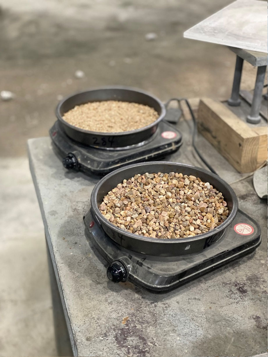
A good example of what I like to call “dumb” concrete would be a concrete ecology block.  This “eco-block” is a block of concrete generally 2 ft wide x 2 ft tall x 4 ft long and would typically cost $375 to $425 per cubic yard.  They have a groove on the side, and they are stacked and interlocked to create wall systems generally used to separate material stockpiles.  These wall systems are common at ready-mix operations separating the various rock and sand aggregate materials used in batching concrete.

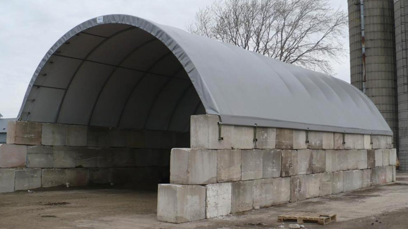
We call this “dumb” concrete because it is such a simple concrete structure typically with only a single lifting anchor cast into it.  Usually, there is no steel reinforcing, no additional embedded steel components, and no CAD or engineering design work required. The concrete mix design is typically very basic and low strength and generally precasters will have a very simple and inexpensive casting mold to produce these ecology blocks. All in, a precast structure like this will have one of the lowest costs per cubic yard price tag.


COST OF PRECAST PANEL (NON-ARCHITECTURAL)

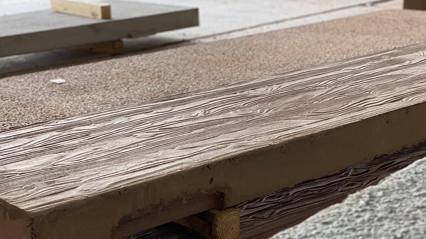
Now, let’s take a step up in complexity.  Precast concrete panels (or slabs) will typically range from $450 to $750 per cubic yard. This is a wider range of cost because there are a wider range of options and factors affecting the total cost. If you consider the differences between a 6” thick panel versus a 12” thick panel, you have much of the same labor costs associated with setting up a casting bed for both thicknesses. You may have more steel reinforcing and obviously, you will have two times the amount of concrete material, but the total labor costs are spread out over twice as much cubic yardage equating to a lower cost per cubic yard for the thicker panel. Other factors affecting the cost could be the amount of miscellaneous steel embed plates or connection components cast into the panel. Are these components plain steel, galvanized steel, or stainless steel?  Are the components stock items readily available or are they custom-built for the project?  Concrete panels also have various finishes and edge treatments depending on the final use of the product.  If the panel requires beveled edges, specific textured finishes, or integral color, obviously these material and labor costs start adding up. As you move into true architectural finishes, the cost per cubic yard can dramatically increase above $750 per cubic yard depending on how specialized the finished product is expected to be.


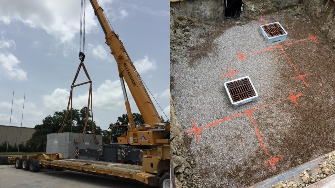
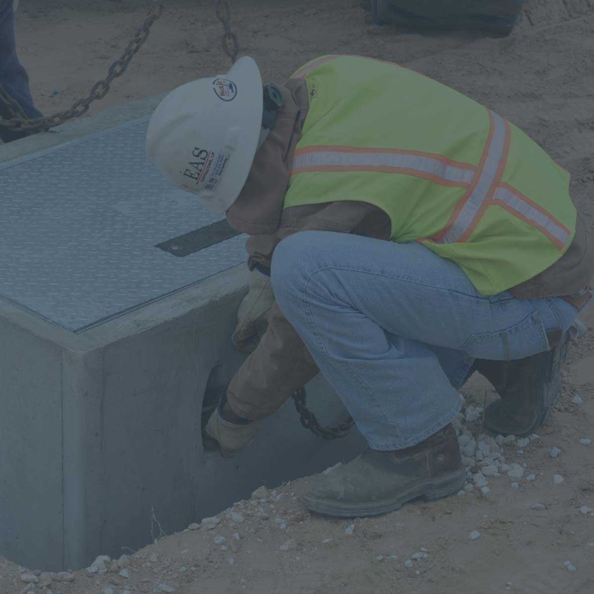
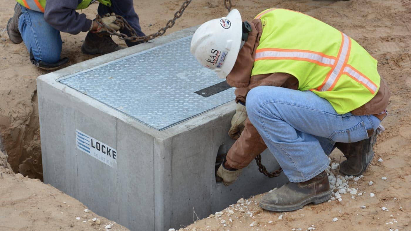
COST OF STANDARD MANHOLES, JUNCTION BOXES, CATCH BASES & INLETS

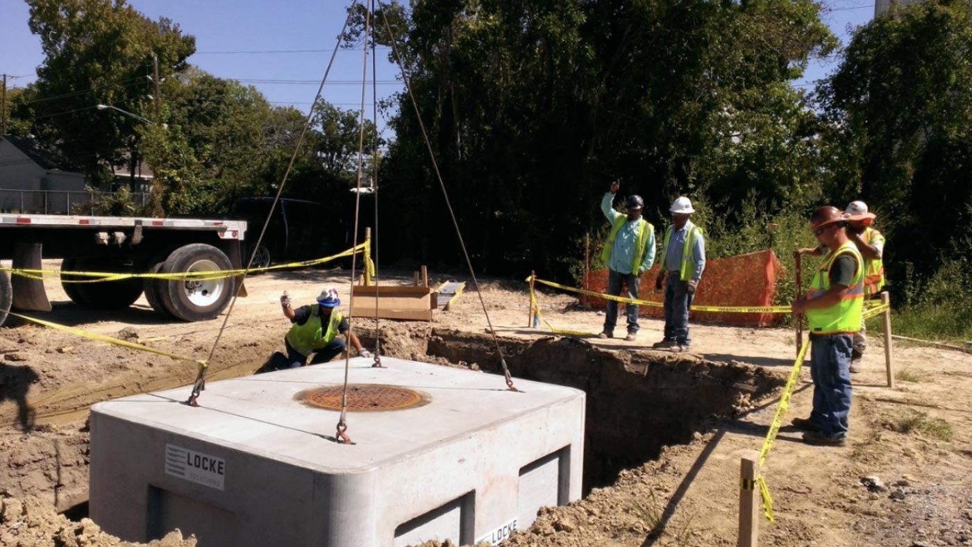
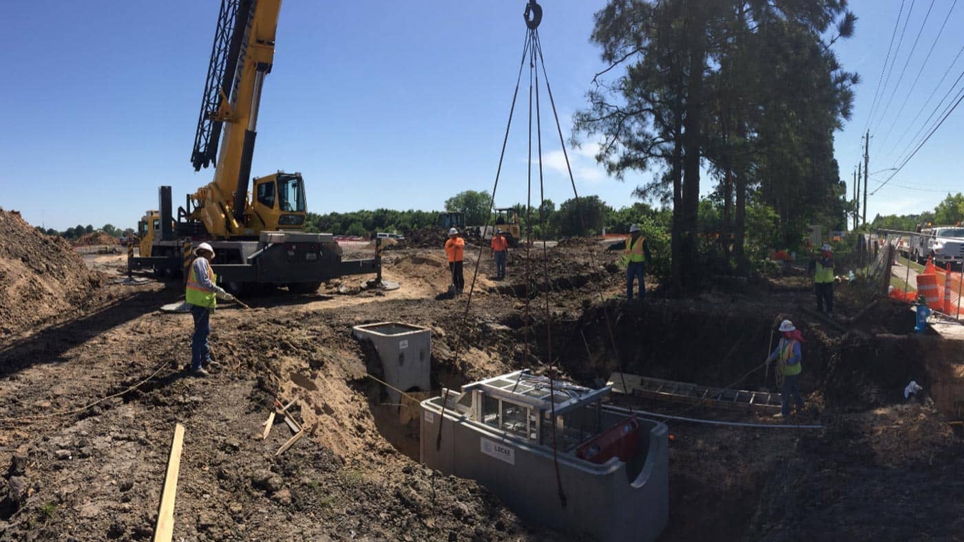
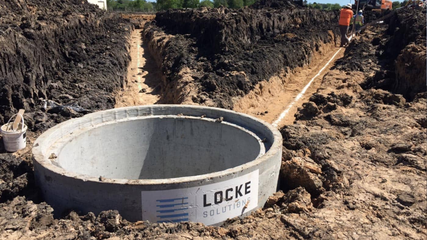
Next, we will focus on the general costs for more traditional precast structures for storm water drainage purposes. Precast manholes, junction boxes, catch basins, and inlets typically range from $700 to $1,000 per cubic yard.  Often these structures are standardized through city or state specifications eliminating the need for design analysis and customized CAD drawings. This standardization also lends itself to standardized casting molds and more repetitive production processes, which helps reduce labor costs per cubic yard. Except for typically lifting anchors, these drainage structures also have very few embedded components. In addition to this range of costs, most of these structures are accompanied by a cast iron or steel component such as a manhole access cover or drainage grating. A good rule of thumb is to assume $300 to $500 per structure for this cast-iron access component.


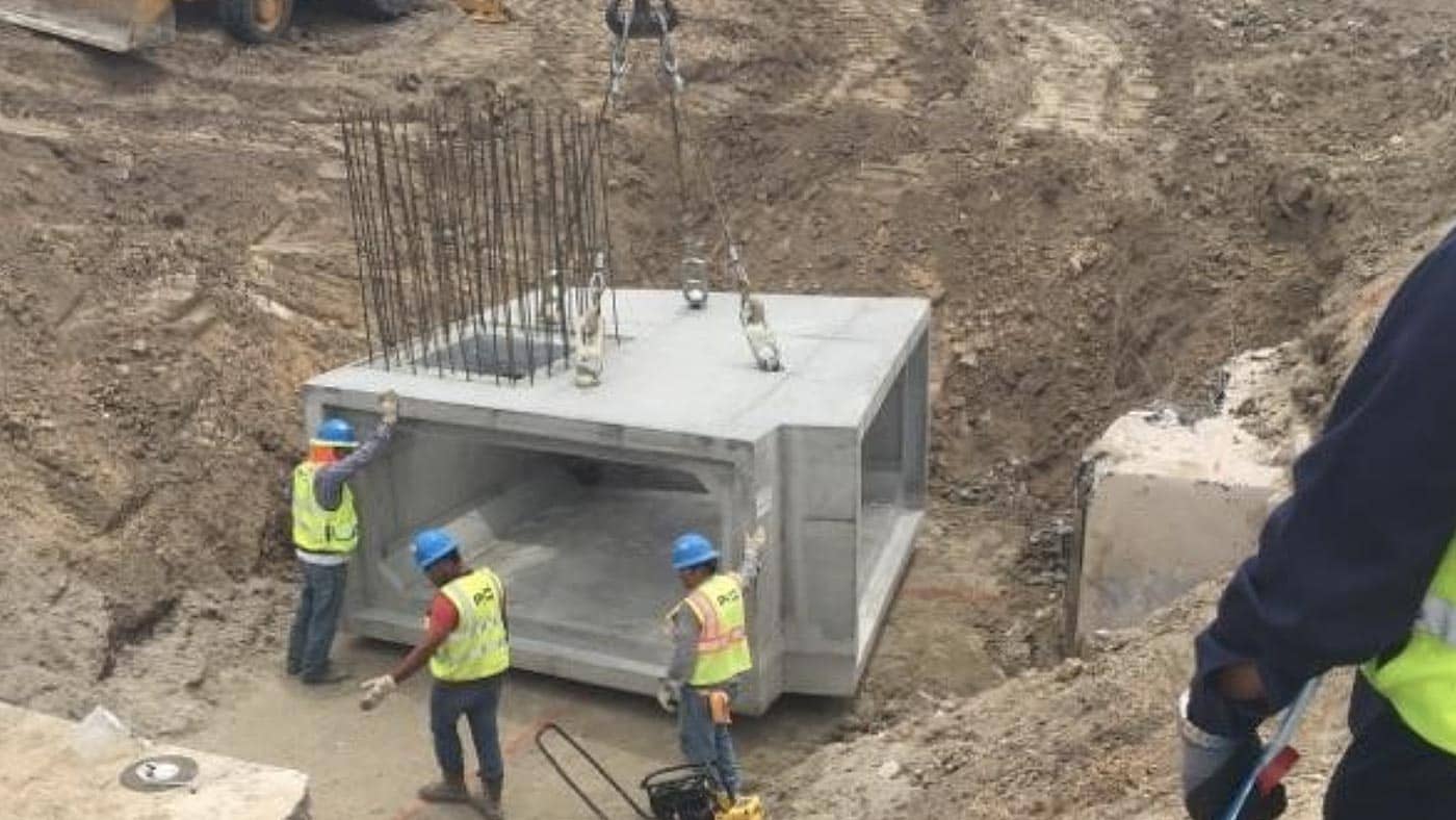
COST OF CUSTOM PRECAST DRAINAGE STRUCTURES

So, what is the impact when a project needs more job-specific concrete structures?  Often the standard “city” catch basin is not sufficient for many different reasons:

  • The size and angle of connecting pipes require a larger junction box base.
  • The traffic loading conditions are heavier than standard HS-20 loading.
  • The top elevation of the structure is critical and needs to be exact.
  • The storm water could have contaminants requiring a more durable concrete mix or internal coating.
  • The surrounding soil conditions may warrant sulfate-resistant concrete or an external protective coating.

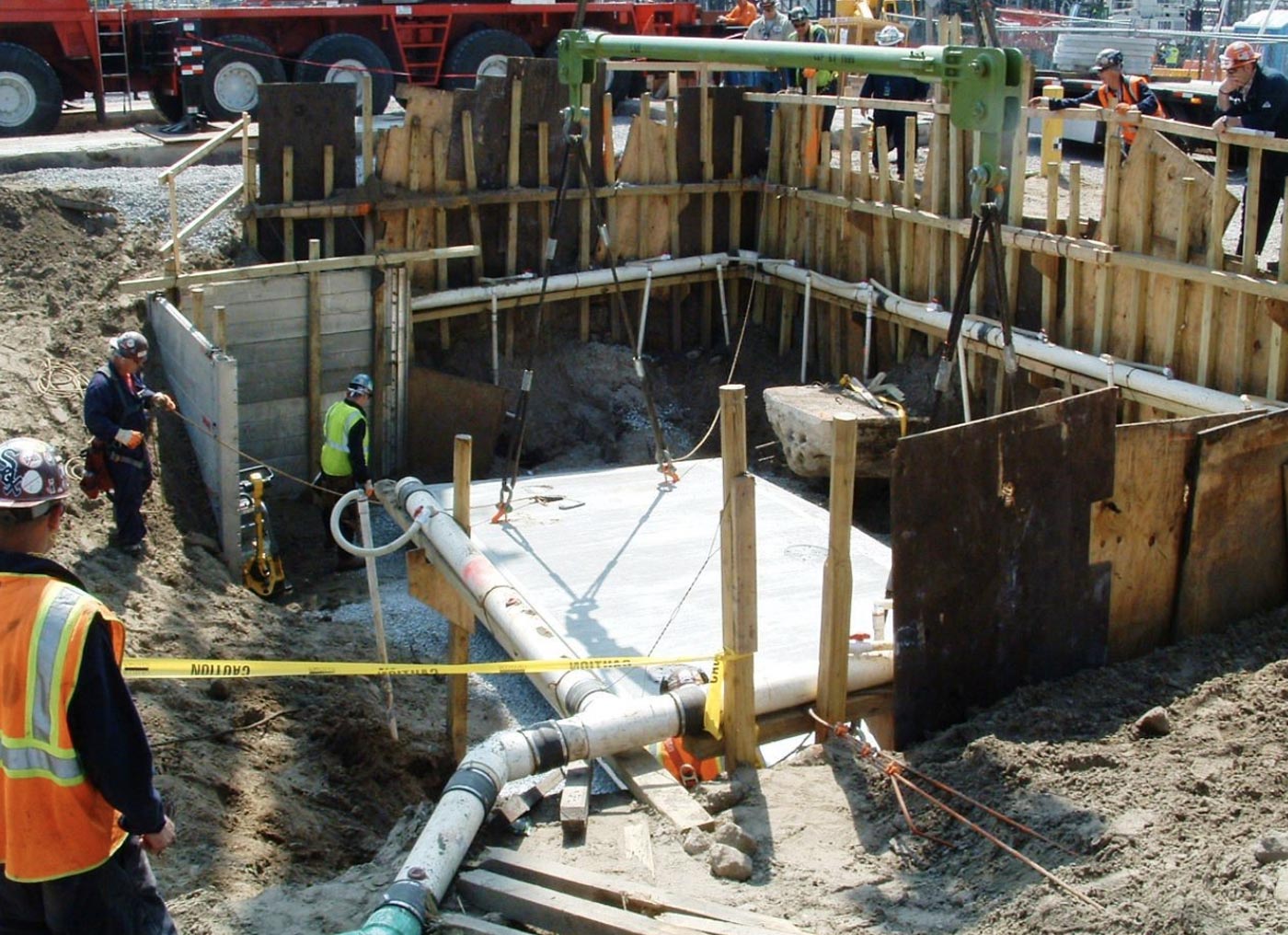
Whatever the reason, when there is a need for a more specific structure, often times a more labor intense setup for the casting mold is needed along with additional engineering and CAD work. The upside in this situation is getting a precast structure to fit the exact need of your project versus modifying your project requirements just to accommodate a standard catch basin size. The downside is the custom precast structure will likely cost a little more and require a longer lead time. As you can see, there are several factors that can influence the cost of a custom concrete drainage structure, but the general range of cost is $750 to $1,100 per cubic yard of concrete…and again, don’t forget the additional $300 to $500 per structure for the steel access components.


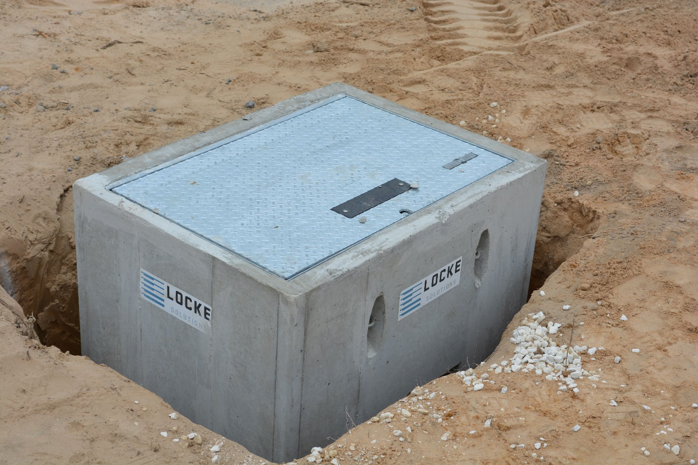
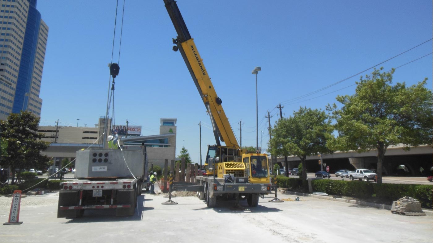
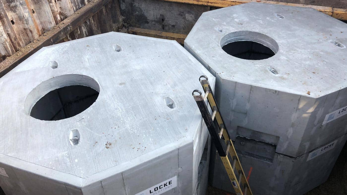
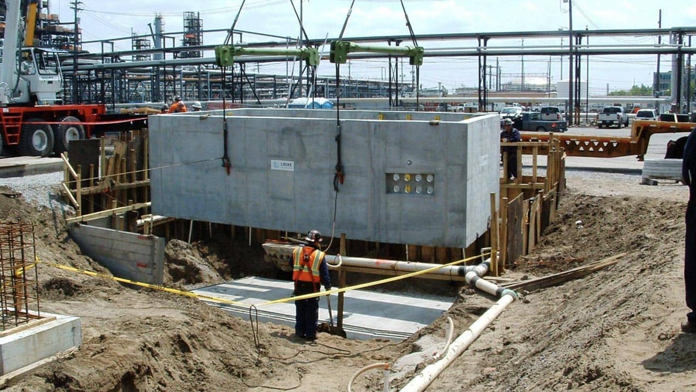
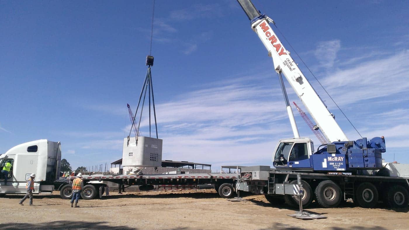
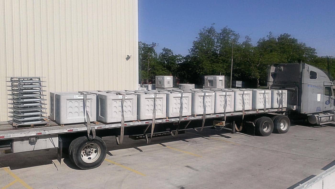
COST OF STANDARD UTILITY VAULTS, ELECTRICAL MANHOLES, COMMUNICATIONS MANHOLES, AND HANDHOLES

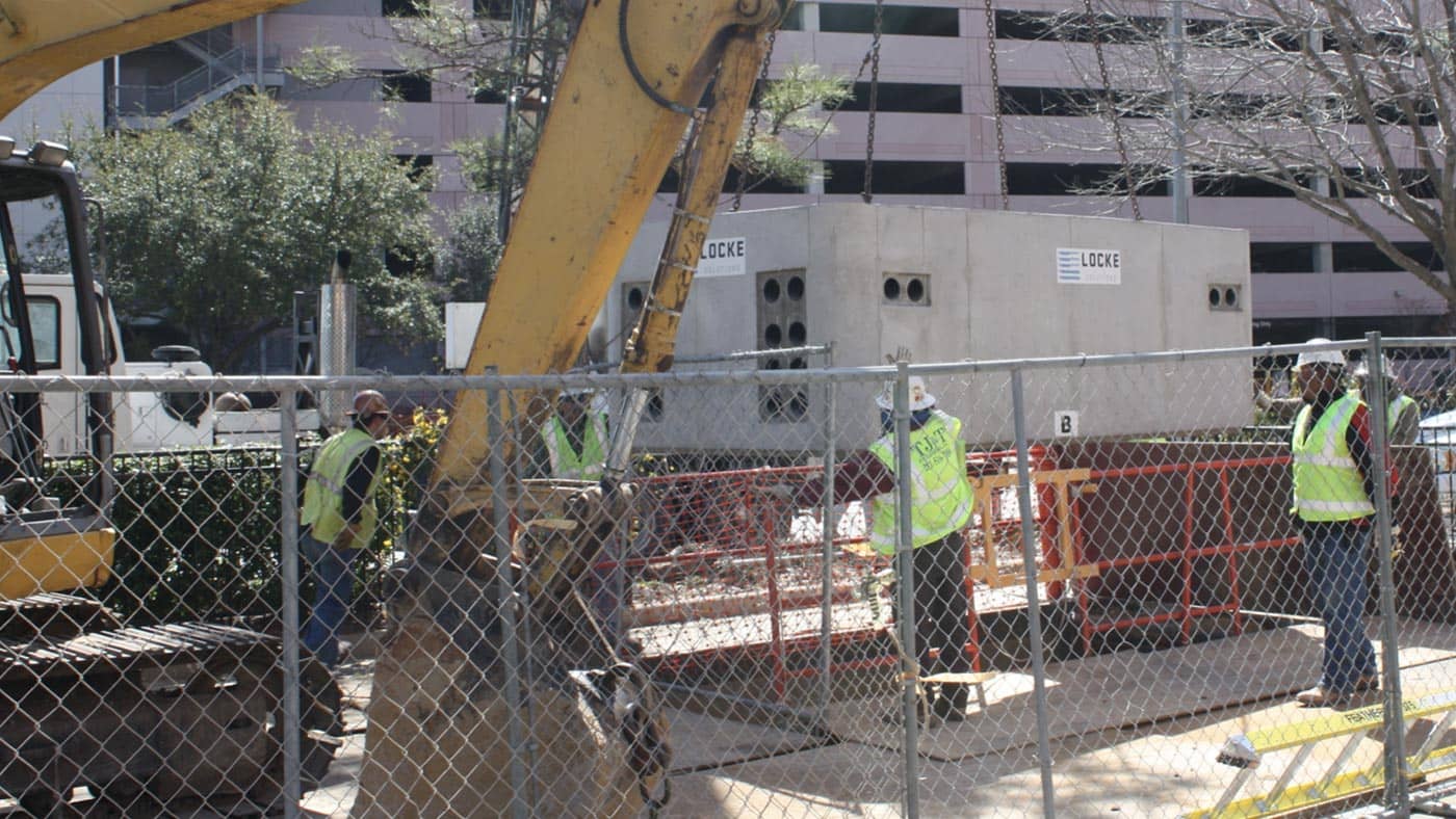
Taking another step up in complexity, we will look at structures typically used in the “dry utility” market for power, electric, and communication distribution underground. The typical cost for utility vaults, electrical manholes, communication manholes, and handholes ranges from $700 to $1,100 per cubic yard. Although these structures can be very similar to standard precast drainage structures, they typically require more embedded items to accommodate the connection with buried conduit and to help facilitate the installation of electrical or communication wires. These embed items could include anchors for pulling cable, electrical grounding devices, conduit couplers are known as terminators, cast-in threaded inserts to accept bolts for equipment installation, and floor sumps to aid in pumping water out of the structure. Another large cost associate with these utility structures is the access cover or hatch. With the need to access these structures more often, the access hatches are typically galvanized steel or aluminum and require more safety features than a typical stormwater manhole. These access hatches can vary significantly with size, material, and load rating being the primary cost differentiators. The cost for these hatches could range between $300 to $1,500 per structure with a smaller 2 ft x 2 ft hatch on the lower end and a 4 ft x 8 ft on the higher end of the cost spectrum.


COST OF CUSTOM UTILITY STRUCTURES

As is the case with custom drainage structures, the cost can vary for underground concrete utility structures with more customized sizing and features.  Some of the common factors to impact the cost include:

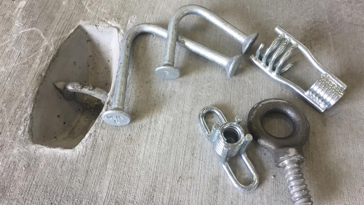
  • The type of support and racking system used to support cables.
  • The required pulling capacity and material of pulling irons.
  • The configuration of the sump to facilitate pumping of the structure.
  • Depth of the duct bank requiring a deeper structure and creating higher lateral earth and water pressures on the vault.
  • Traffic loading conditions greater than normal HS-20 loadings such as heavy equipment, aircraft, heavy-duty forklifts, and rolling cranes.
  • Requirements for non-ferrous reinforcement.
  • Requirements for grounding devices integral to the precast vault.
  • External coatings or the use of additives to seal off micropores in the concrete due to contaminants in the soil.

Certainly, these different factors can significantly impact the cost, but a general range of cost for these custom utility structures is $750 to $1,300 per cubic yard plus the addition of $300 to $1,500 per structure for the access hatch described in the previous section.


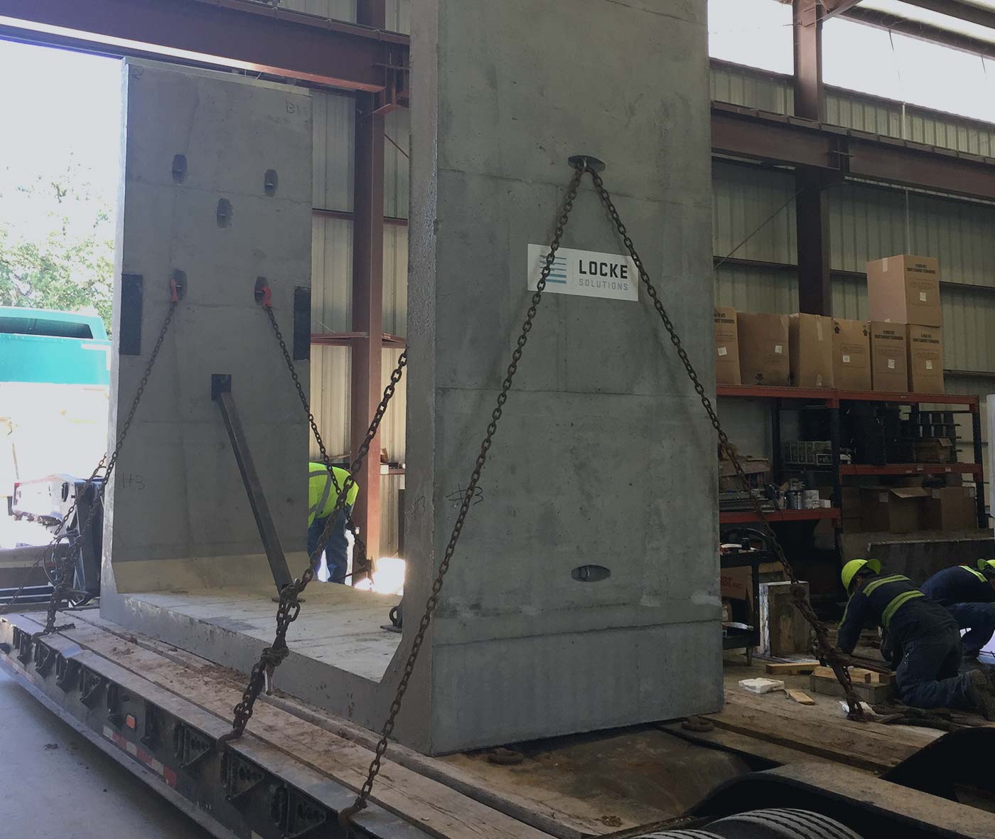
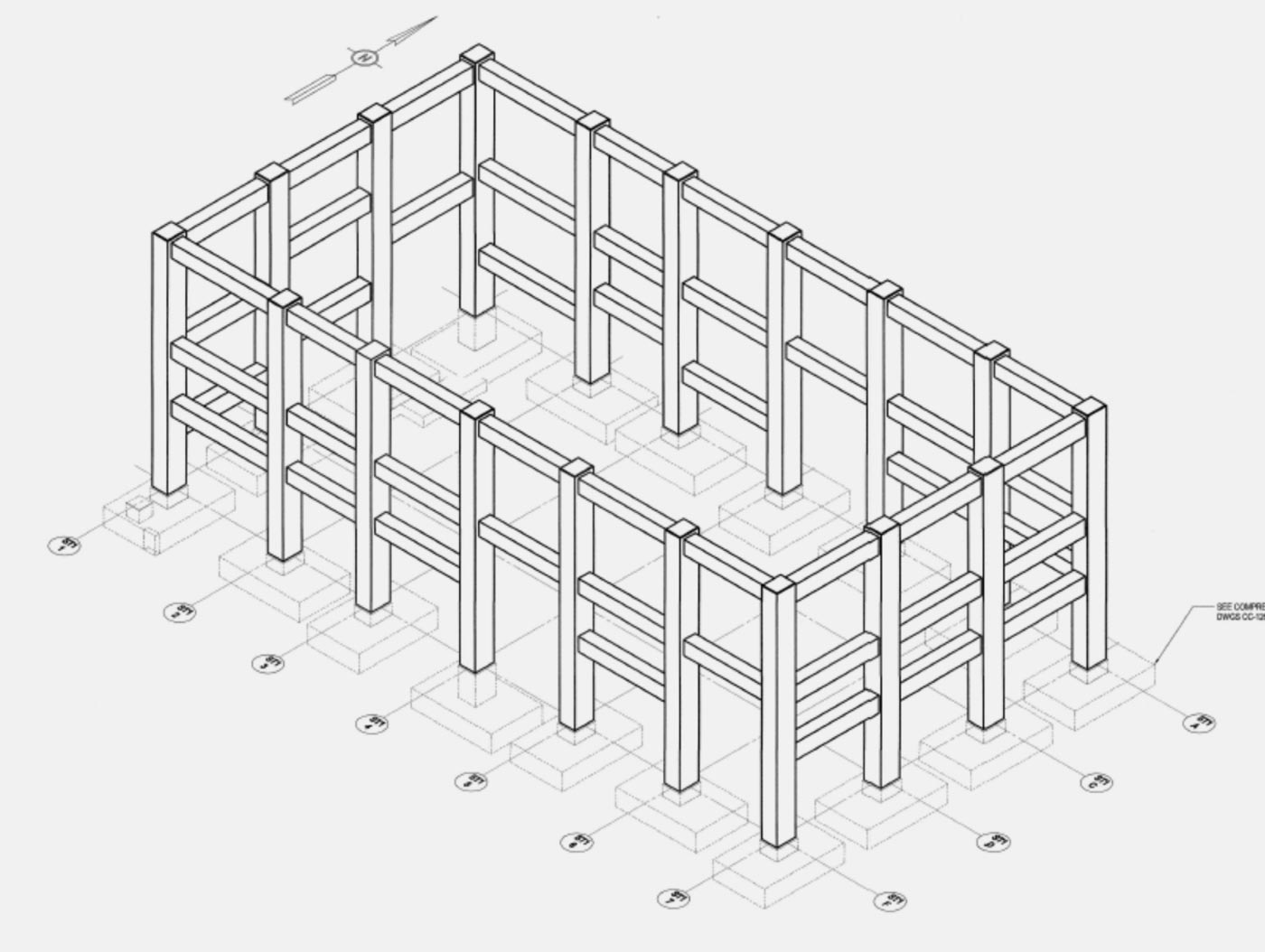
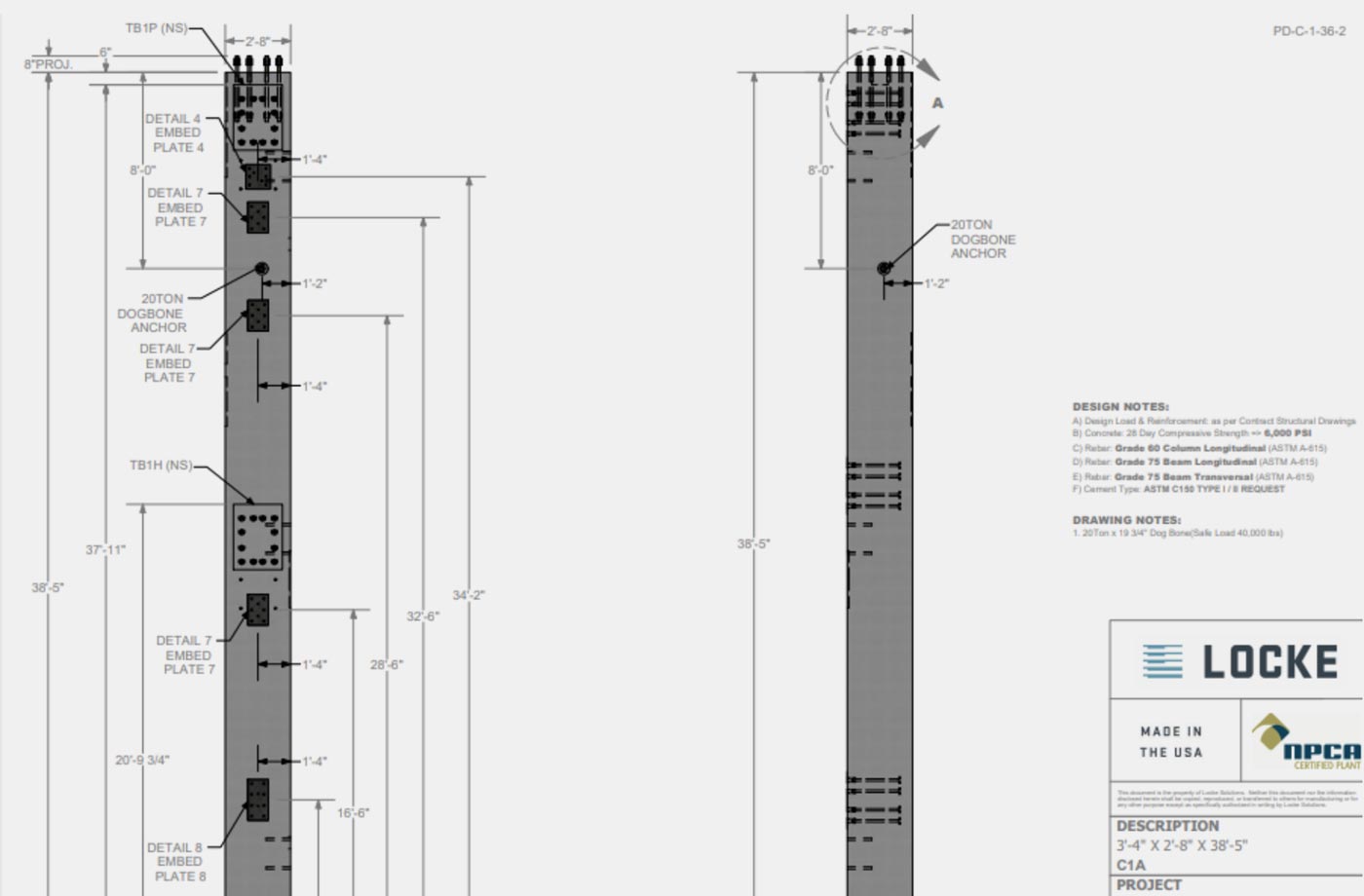
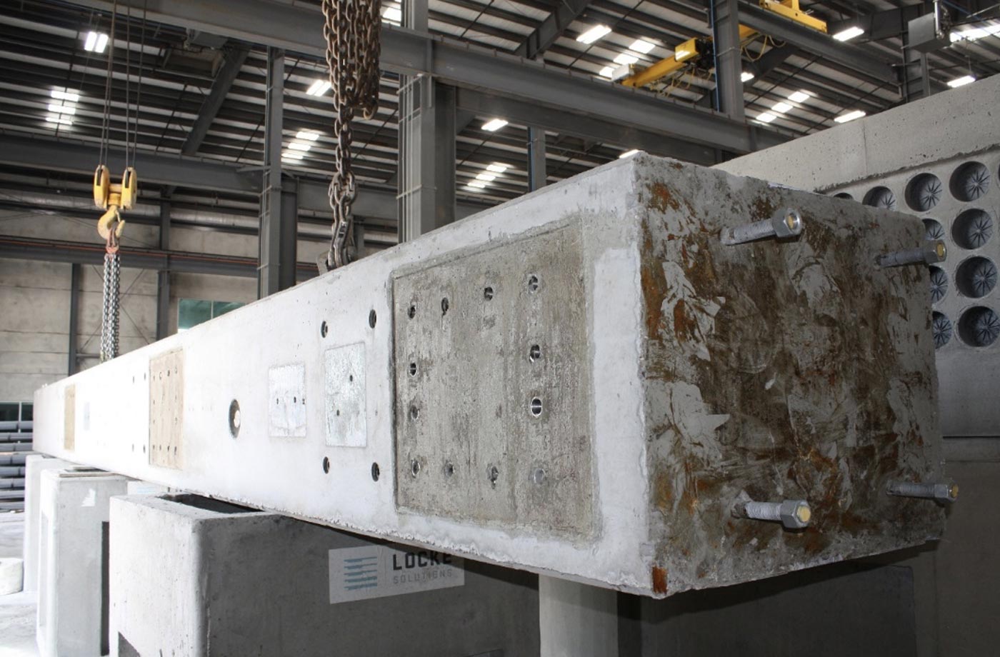
COST OF CONCRETE SPREAD FOOTINGS (FOUNDATIONS)

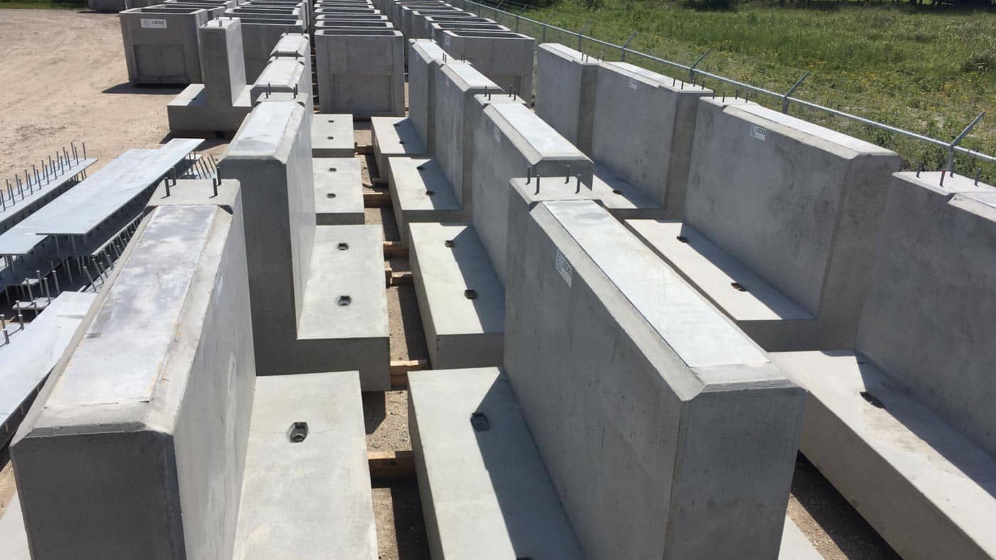
Precast concrete spread footings come in various shapes and sizes with a cost range of $800 to $1,000 per cubic yard of concrete.  Normally, these footings will have a galvanized steel plate or anchor bolts embedded which will add another $50 to $300 in cost for each pedestal mount associated with the footing. The type of steel, the thickness of the plate, and the type and size of anchor studs all have an impact on the cost of embedded weld plates. Typically, these embedded weld plates will cost between $50 to $150 for each one.  Cast in anchor bolts can vary greatly depending on the diameter, length, and grade of steel required.  Typically, anchor bolts will cost between $20 and $65 each, and generally spread footings will have 4 to 6 of these anchor bolts for each support pedestal.  Spread footings can come in an endless variety of configurations and sizes. The base slab of the footing can be manufactured in rectangular or circular dimensions at any thickness while the raised pedestal of the footing can also be produced in a round or rectangular shape at any height necessary.  Sometimes the design requires to have multiple pedestals located on the same base footer slab, which can easily be accommodated in the precast setup. Another important note, if the project has several spread footings of the same dimension, there can be significant cost savings on the casting mold setup. It is a good idea to consult with your local precaster to determine the most economical options when determining your layout of spread footings on the project.


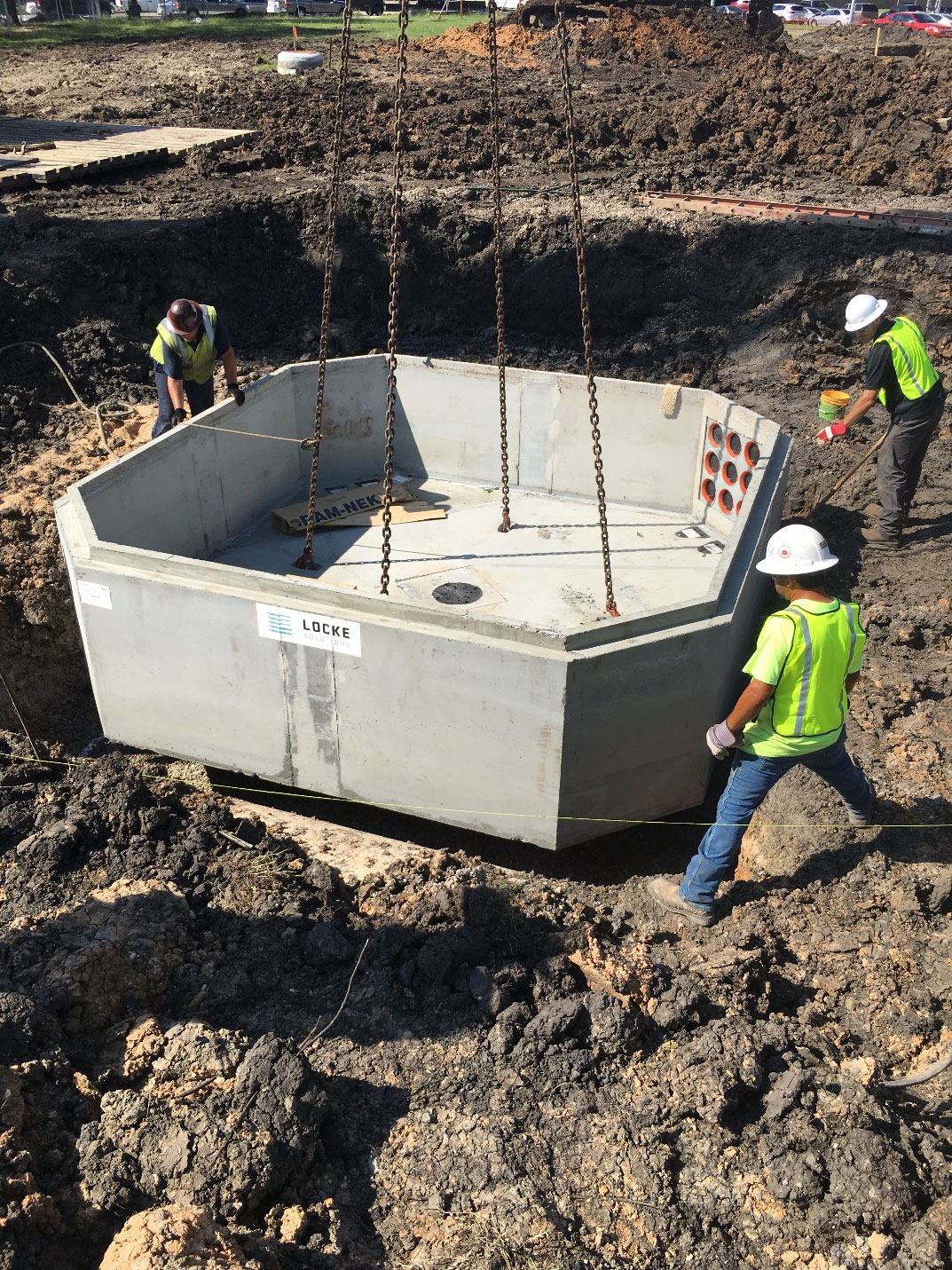
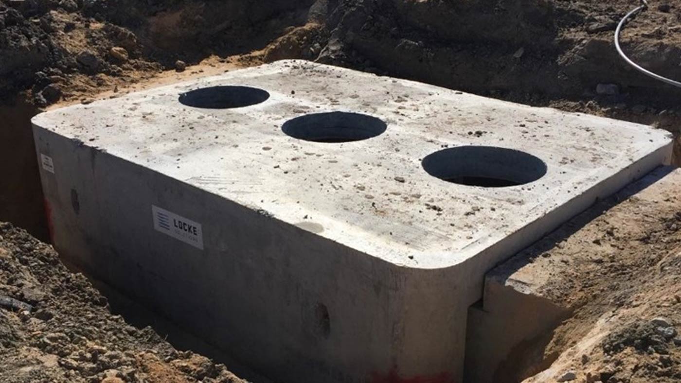
COST OF CONCRETE SUMPS

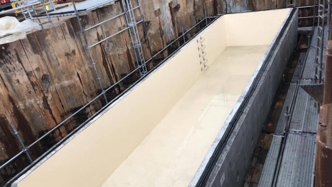
The cost of concrete sumps will typically range between $750 to $1,200 per cubic yard. Precast concrete sumps come in a range of sizes as small as 2 ft x 2 ft up to mega-size sumps with length and width dimensions of 30 feet and greater. Generally, these larger sumps can be difficult to precast because of challenges in shipping. When the smaller dimension of width or length is greater than 16 feet, the costs of shipping start increasing exponentially due to the required permits and escorts needed. If the volume of the sump is more critical than the shape, precast can normally be incorporated in the design by creating a rectangular design and limiting the inside width of the sump to 10 ft. The required volume of the sump can be attained by increasing the length and depth and you get the benefit of reduced shipping costs (shipping costs are discussed below in this article). Sumps will normally have multiple manway access openings along with vent pipes and inspection ports. Depending on the type of material (aluminum, steel, cast iron) and the size of the access, the cost will range between $300 to $1,500 for each access. The cost of vent pipes will range between $40 to $100 each depending on the size and material. Another potential cost associated with sumps can be the lining of the internal walls. In many cases, the water contained in sumps can have abrasive chemicals requiring a sprayed-on liner coating or a liner material integrally cast into the concrete wall. These liner systems can vary widely depending on the application needed, but internal liners can cost between $20 to $60 per square foot of surface area.


COST OF CUSTOM TRENCH

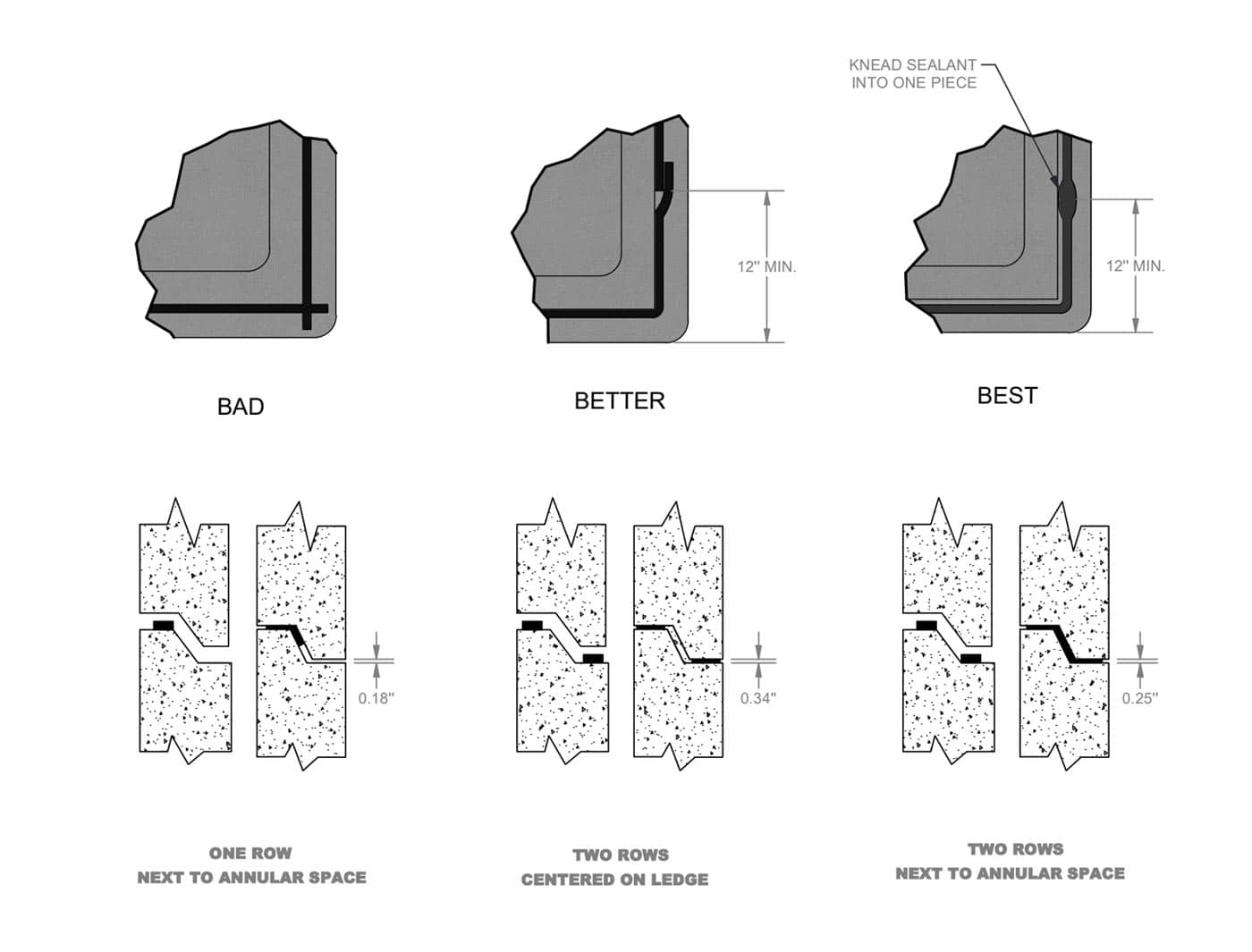
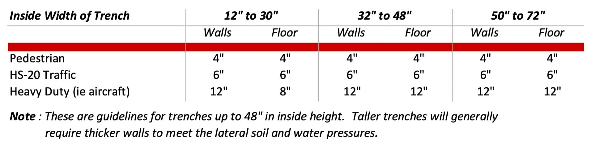
Concrete trenches are used for various applications including for the protection of utility lines such as water or air, chemical piping, electrical and communication lines, power transmission lines, or for the conveyance of storm water. We will separate these trench systems into two categories, utility trench, and drainage trench, and give you a cost breakdown for each. Trench systems are typically priced out per linear foot, so before we dive into the cost per cubic yard of concrete, let’s tackle the next question you might have. “How thick should we estimate the walls and floor of the concrete trench to be?”

This question has a wide range of answers, so we have created a chart below to give general guidance.

COST OF UTILITY TRENCH

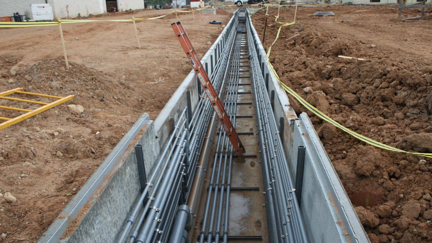
The cost of concrete utility trenches will generally range between $800 to $1,100 per cubic yard for the base portion of the trench.  The main factor impacting this range of costs is the system for securing racks or supports for the piping.  This can be as simple as providing threaded inserts cast into the walls to accept bolts.  Other methods could include providing a cast in support system such as Unistrut or providing cast in weld plates to allow for a welded connection of pipe supports.  The materials can range from standard black steel to stainless steel, to non-metallic materials such as fiberglass.  The length between the necessary pipe supports is generally dictated by the type of piping material used and how much support is necessary.  We see support systems ranging anywhere from 5 ft to 20 ft between supports.

COST OF CONCRETE STORM WATER DRAINAGE TRENCH

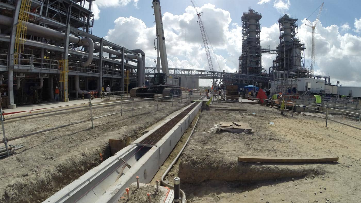
There are fewer variables with trenches used solely for the purpose of water conveyance.  The cost of concrete drainage trench can range between $750 to $1,100 per cubic yard of concrete.  

Drainage trenches typically have a steel or iron grating system to allow for storm water runoff to enter the trench system.  Again, the loading conditions and the width both play a big role in determining the ultimate cost of these grating systems.  The range of costs for drainage trench grating systems is $100 to $800 per linear foot of the trench, which is very much dependent on the width of the trench.  


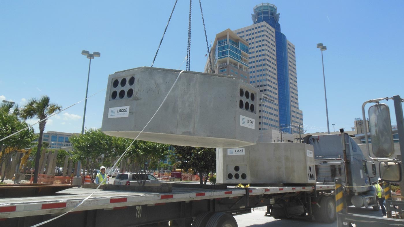
COST OF DELIVERY FOR PRECAST STRUCTURES

So now you know how to get a close estimate of the cost of your precast structure…your next question is “How much extra will I have to pay to ship my precast concrete structure to my job site?”  We are here to help answer that question as well and you can find information here about Best Practices for Shipping Precast Products.

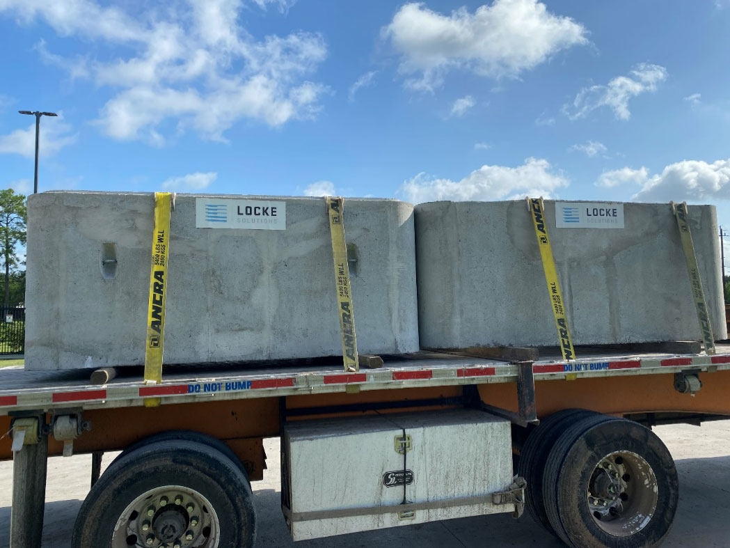
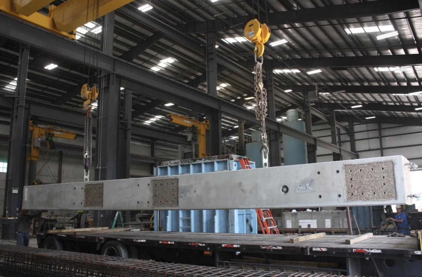
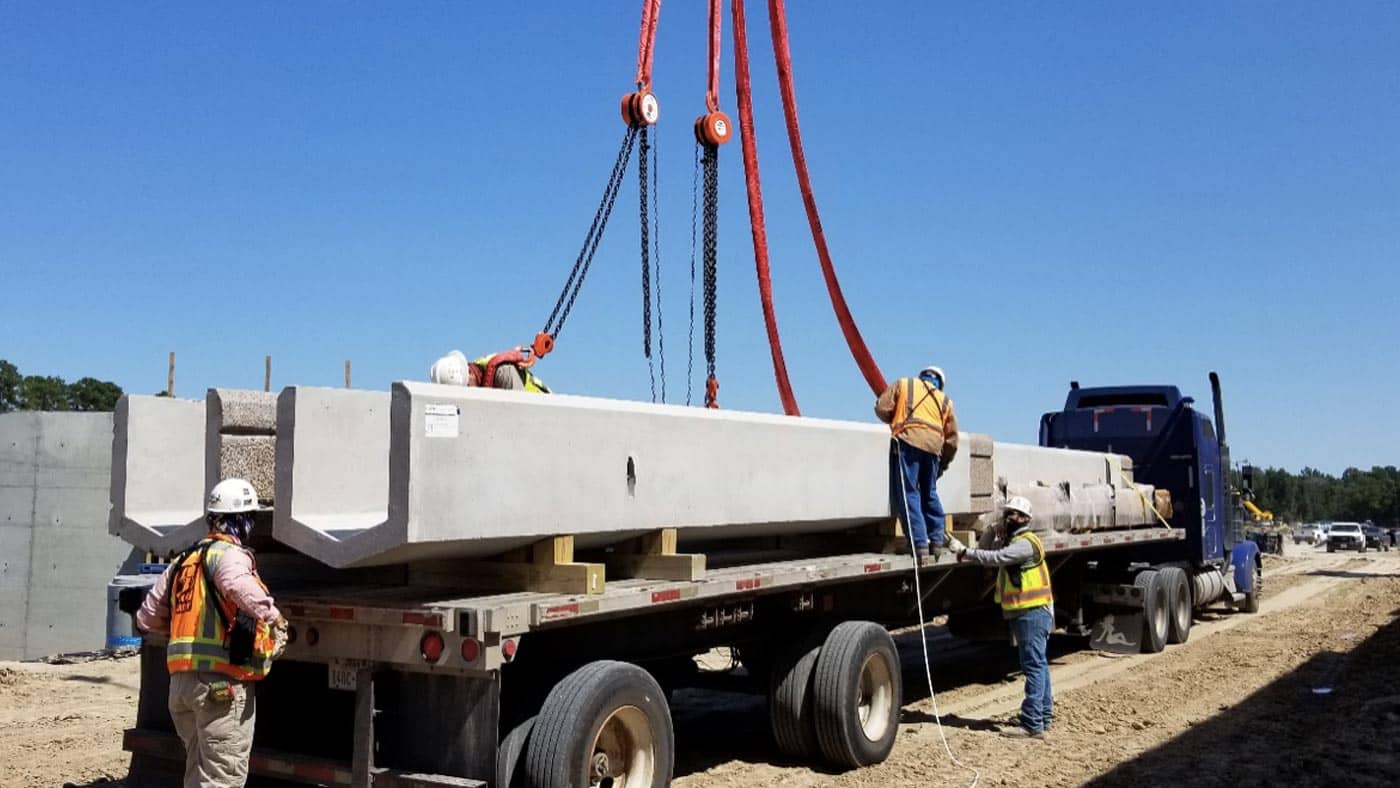
Just like anything else being shipped, the cost for delivery is a function of weight and distance.  Being able to utilize the full capacity of a flat-bed truck will reduce your cost per cubic yard of concrete. Typically, flat-bed trucks can hold about 46,000 lbs, so filling up the truck as close to this load capacity is ideal. The Department of Transportation rules do not allow you to add additional products to a truck if it starts to exceed its load limit. The rules allow shipping of a single structure that exceeds the load limit, but in that case, there are additional fees associated with permitting the load. These extra fees are incurred as a way of “taxing” heavier loads and providing more funding for roadway maintenance.

Assuming the structure is within normal shipping parameters, less than 9 ft wide and less than 46,000 lbs, you can expect to pay $575 to $850 per load if you are within a 100-mile radius. The cost increases the further away the job site is from the producing plant. Delivery cost ranges from $850 to $1,125 per load at 100 to 200 miles. As you get farther than 200 miles, costs can vary quite a bit depending on the trucking market. Interstate trucking brokers can potentially obtain backhaul rates that dramatically reduce shipping costs.


LESS THAN FULL TRUCKLOAD DELIVERIES

In the case your shipment is significantly less than a typically 18-wheel flat-bed load, there are smaller trucks and trailers available at a reduced rate. For instance, if you have a 7,000 lbs structure, your delivery cost would be around $450 to $700 per load within a 100-mile radius.


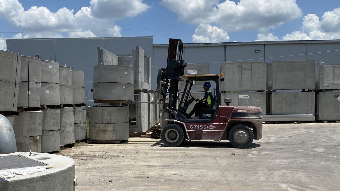
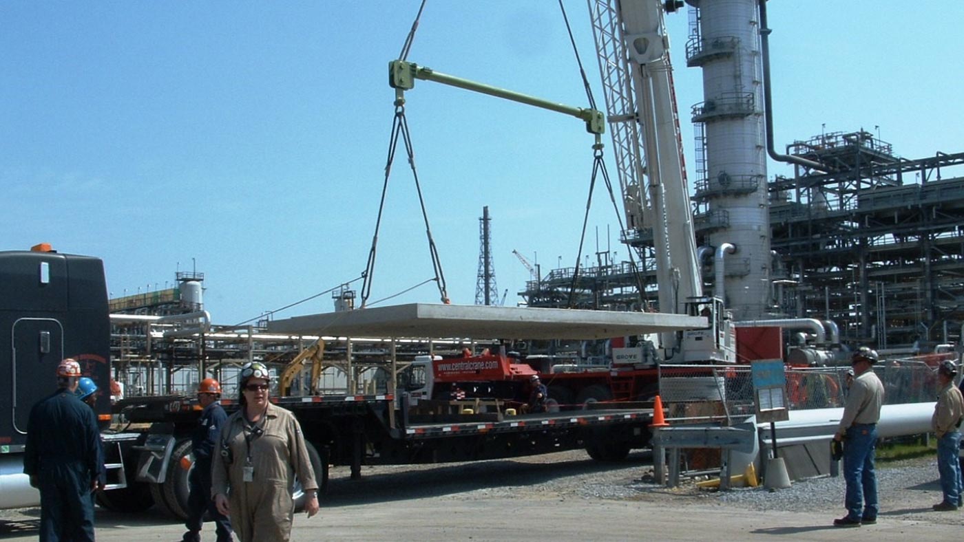
HOW BIG AND HEAVY CAN YOU GET?

A common question we hear is “How big and heavy can a precast concrete structure be and still be able to ship it?” Usually, people are surprised to hear we can ship structures over 200,000 lbs and over 100 ft long. Yes, the cost starts to increase dramatically as you get into these megastructures, but here is some guidance on what to expect.


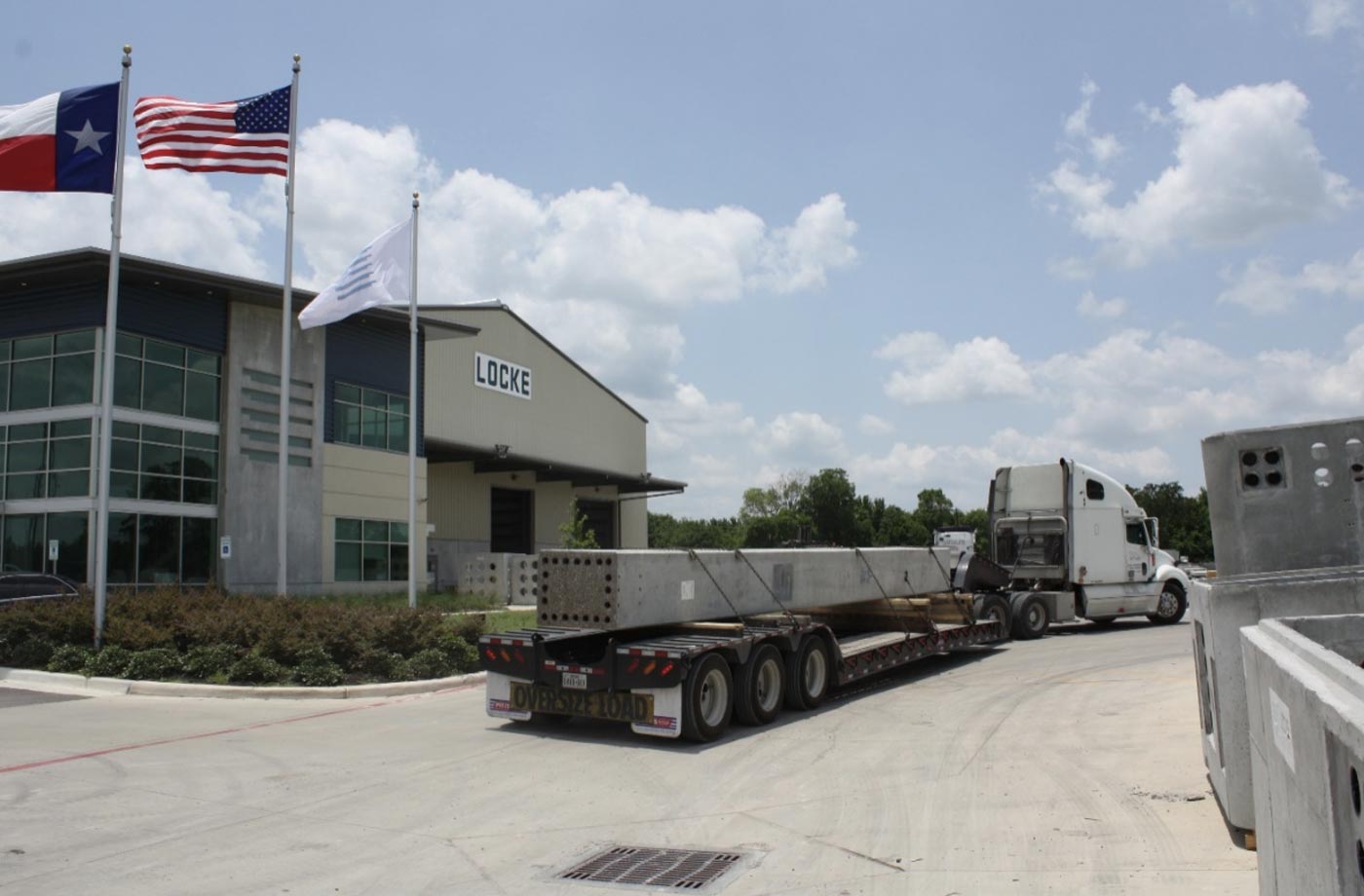
OVER-WIDTH DELIVERIES

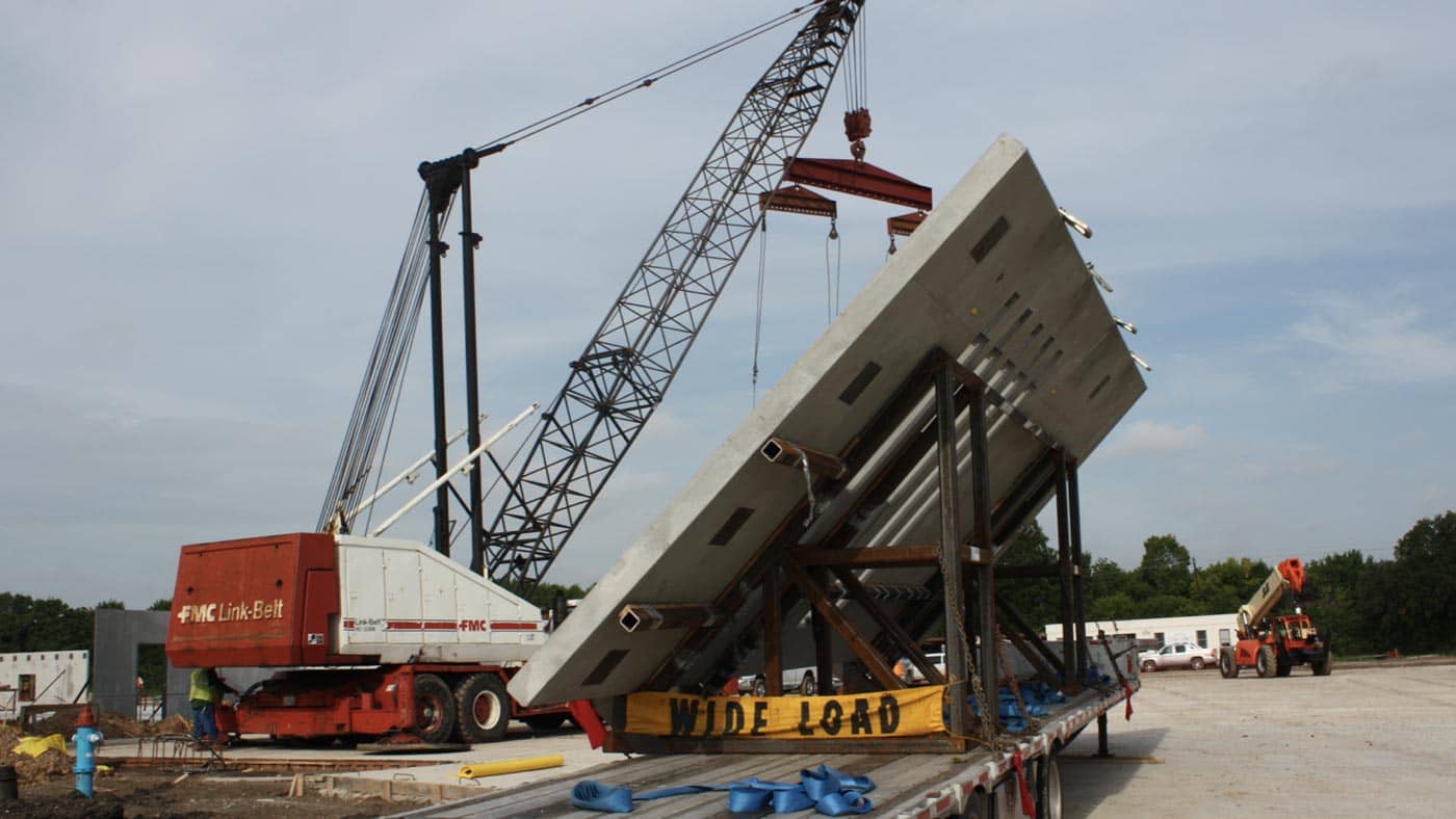
The standard shipping width not requiring a permit is 8 foot 6 inches or less. A structure that is over 8’-6” wide, but not more than 12 feet wide requires an over width permit ($550 to $825). Structures over 12 feet in width, but not more than 14 feet wide, require a permit and police escort ($800 to $1,400). Structures over 14 feet, but not more than 16 feet in width require a permit and two police escorts ($1,700 to $2,000) and shipments with product over 16 feet in width require permits, escorts, and close coordination with the Department of Transportation and can cost more than $2,200.


OVER-HEIGHT DELIVERIES

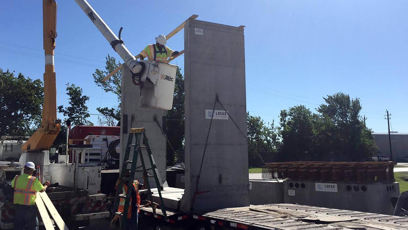
Similarly, to the width scenario, a truckload with a total height of 14 feet or less from the ground up is considered standard. Shipments (including the product and trailer height) taller than 14 feet are more complicated and it depends on the route from the producing plant to the jobsite to determine the cost. Typically, taller shipments must be re-routed to avoid bridges and could potentially require a bucket lift escort to raise overhead power and communication lines during the shipment. The cost of this is relative to what type of height obstructions are between point A and point B. Fortunately, most precast concrete structures can be designed and broken into shorter sections to avoid these situations.


OVER-WEIGHT DELIVERIES

We all know concrete is heavy…and strong.  That is part of why it is such a great building material, but it can create challenges when shipping it.  As mentioned above, the typical flat-bed truck has a load capacity of about 46,000 lbs depending on the truck.  A single structure heavier than the load capacity will require an overweight permit.  This overweight permit varies, but for a load between 46,000 lbs and 60,000 lbs, this permit cost can range between $300 to $350.  As the weight continues to increase, the cost of permits will increase and potentially other costs will come into play as you consider other factors such as the route of the delivery, load capacity for bridge crossings, and weight per wheel on the trailer.  As you start getting above 85,000 lbs for the load, specialty trailers with extra wheel axles are needed to handle the load.  As you get above 175,000 lbs, even more specialized equipment is needed to handle the shipment and the extra costs can range from $5,000 to $20,000 per load depending on the length, width, and height.   


These are guidelines meant to help in putting together cost estimates for your next precast concrete project.  As you can see, there are quite a few variables that can impact the overall cost but working with your local precaster when designing your project, you can eliminate unnecessary costs and build in great features to reduce your onsite installation costs.  

We hope this article was helpful.  Please send in your questions to info@lockesolutions.com and we would be happy to help answer them.

achive.php: you are in the loop
slug: precast-concrete-joint-sealants
post_type:post

How do you seal up precast concrete joints and what are the most common concrete joint sealants used?

Manholes, Catch Basins, Sumps, Culverts, and Trenches are just a few structures that often require joint sealants. To ensure that the joints are properly sealed, it is important that the correct steps are followed and that the right type of joint sealants are used.

Before precast concrete joints can be sealed, it is important to check that the joints are properly prepared for the application of the joint sealant. It is crucial to ensure that the joints are level and completely clean and free of any dirt or debris. At this point, a primer may be used to help create a more adhesive bond between the sealant and the concrete surface. Once the joints are inspected, the application of the joint sealant can begin. 

“When sealing precast concrete joints, it is important that the joints are clean and completely straight. The sealant must also be applied properly to the joints. If this is done correctly, the structures will not leak, and this is the main goal with sealing precast concrete joints.”

-Andy Gemmill

BUTYL-RUBBER BASED SEALANT

Butyl-Rubber-based sealant is a popular precast concrete joint sealant as noted in ASTM C990 “Standard Specification for joints for Concrete Pipe, Manholes, and Precast Box Sections Using Preformed Flexible Joint Sealants.” It often comes in strips and has a sticky texture similar to the consistency of tar. Press-Seal, ConSeal, and Henry are companies that provide Butyl-Rubber-based preformed joint sealants meeting this ASTM C990 specification. 

Installation for Butyl-Rubber Joint Sealants

The two most common questions by contractors using this type of joint sealant are:

  1. Where should the preformed sealant be placed on the joint?
  2. What is the correct method for connecting the joint sealant to create a continuous seal?

Location: The most common joint profile where butyl-rubber joint sealants are used is the single offset shiplap joint as shown below. As you can see, there are several acceptable positions for placement of the sealant, but a good rule of thumb for other joint profiles is to place the joint sealant as close to the center of the joint as possible.

Connection: These butyl-rubber-based preformed sealants typically come in pre-cut rolls or strips and when placing on the precast structure, it will require multiple pieces. To prevent a gap in the seal along the joint at this connection point, it is recommended to connect the two sections by kneading the ends together and creating a similar cross-section profile at the connection. It is also recommended to avoid connecting two pieces of sealant at the corner of a structure.


Installation of Sealant around a Corner


The outer wrapper on the sealant should be left on to keep it clean and prevent over-stretching while placing the sealant along the joint. Once the strips are in place, the wrapper may then be removed prior to placing the next precast section in place. After setting the precast sections together, the butyl-rubber sealant will compress, and it is normal for the sealant to slightly ooze out from between the joints. Depending on the ambient conditions, the rate of compression will vary, and it is recommended to wait about 10 minutes to allow the sealant material to reach maximum compression.

If the use of a primer is required before placement of the butyl-rubber sealant, several options are available including ConBlock SH, CS-50, and CS-75, all of these provided by ConSeal with different features.

  • ConBlock SH – this primer is applied in advance and developed to absorb into the concrete and react with the calcium hydroxide turning it into a hardened crystal.
  • CS-50 – a solvent-based liquid butyl primer applied in advance filling in the micropores of the concrete with rubber creating a great bond for butyl-rubber sealants.
  • CS-75 – a water-based adhesive primer that leaves a tacky surface applied at the time of sealing.

Butyl-Rubber based Joint Sealants:


HYDROPHILIC ELASTOMERIC JOINT SEALANT

Another type of joint sealant is a hydrophilic elastomeric joint sealant. Examples of this type of sealant include Sika’s SikaSwell and ConSeal’s CS-1900 providing a swellable waterstop to seal up precast joints and concrete construction joints. These sealants are provided in various forms and can be applied with caulking guns or placed as strips similar to the butyl-rubber preformed strips. The technology with these sealants provides a swelling effect of the sealant when it comes in contact with water creating a watertight seal in the connecting joints.

Hydrophilic Elastomeric Joint Sealants:


GROUT CONNECTION

Joints between precast concrete sections are sometimes connected using a cementitious grout. Grout is a mixture of water, sand, and cement that is mixed and can reach compressive strengths of 6,000 to 10,000 psi at 28 days of curing. Often cementitious grouts are used to bed the joints between precast sections or to facilitate a structural connection with projecting reinforcing steel embedded into a pipe sleeve. Whether creating a bed of grout or pumping the grout into open cavities between precast sections, the joint should be prepared to remove all dirt, oil, grease, and other loose material that could prevent a strong bond with the grout. The joints should then be carefully aligned, joined together, and any excess grout that squeezes out can be wiped away.

There are numerous manufacturers of cementitious grout, but below is a shortlist of common materials.


FUEL AND OIL RESISTANT JOINT SEALANT

Occasionally there is a need to provide joint sealants able to resist certain chemicals such as fuels and oils. When working on industrial sites or dealing with stormwater or sump systems with potential hydrocarbon contamination, it is critical to pick the right joint sealant that can hold up to the potential chemicals. Each situation is different, but here are a few joint sealant products that can be useful in these situations.

Regardless of the chemicals you are encountering, more than likely there is a suitable joint sealant to handle the job.


Stay tuned for the next article!

achive.php: you are in the loop
slug: common-problems-with-precast
post_type:post

Precast concrete can present problems. However, there are proactive measures that can be taken and several solutions to combat many of these challenges.

Here are some of the most common challenges we hear associated with precast concrete structures:

  1. Sealing the Joints
  2. Shipping the Product
  3. Offloading & Rigging Concerns
  4. Preparation of Subgrade
  5. Lack of Flexibility
  6. Repairing Spalls or Cracks

SEALING THE JOINTS

Problems can arise with the sealing of precast concrete joints. Over time, joints can separate from one another which can compromise and weaken the structure. This problem can occur when joint sealants are not applied correctly. This usually occurs if the joint sealant instructions are followed incorrectly. If the joints are not properly prepared or cleaned prior to applying the joint sealant this can weaken the adhesion between joints and prevent the joints from properly sealing with one another. However, joint sealant problems are usually very preventable. If the joint sealant instructions are followed and all appropriate preparations are made prior to applying the joint sealant such as: ensuring that the joints are clean and free of any dirt or debris along with checking that the joints are properly formed to fit together correctly by conducting a dry fit or checking the alignment prior to the joint sealant application, then the application of precast joint sealants should be successful and problems with the joint sealants should not occur. See more about joint sealant options and installation in our article.


SHIPPING THE PRODUCT

Shipping precast concrete can be challenging and it is should be a coordinated effort between the manufacturer and job site contact. Precast concrete can be difficult to transport due to the weight and potential because of how large the structures can be. For larger structures, specialized trucking and various preparations could be needed to transport the structures. The greater the height, width, and weight of the structures, the greater number of arrangements that are possibly needed to facilitate the transportation. Structures over 8 feet 6 inches wide will require a permit. Structures that are over 14 feet wide require a permit and an escort. Structures that are over 16 feet wide will require a permit and two escorts. Precast concrete structures that are over a certain weight will also need a weight permit. For shipments taller than 13 feet, route inspections must take place and potential bucket lifts may be required to add in avoiding powerlines. The route will be surveyed to ensure it is safe for the structures to travel. Logistically, transporting precast concrete can seem challenging, but utilizing expert hauling companies who understand the DOT rules and who are equipped with the right trucks and trailers can make the delivery seamless. In the event the structure is too heavy, too tall, or too wide to be transported, precast designers can normally split the structure into multiple sections to reduce the weight or size of any individual precast section. There are several methods for creating structural connections between sections of precast in the field. This makes transporting these large structures possible and reducing the lifting capacity needed on site.  See more about shipping best practices in our article.


OFFLOADING AND RIGGING CONCERNS

Another challenge with precast concrete is offloading and properly rigging the structures. Normally, cranes or large equipment are needed to pick up and move the structures. As with any process involving cranes, there is a risk associated with understanding the capacity of the crane, rigging, and lifting devices. It is important that the correct rigging is utilized so that the structure is secure before lifting.

Improper shoring of an excavation can lead to catastrophic failures and should be inspected and engineered if necessary. In the event that a job site has overhead obstructions or there is a question regarding the shoring, it is a good idea to involve the crane company and walk the site before installation. For extremely large structures, lifting diagrams and rigging plans should be created by certified engineers to ensure the structure is lifted properly. Understanding how to correctly rig a precast structure, recognizing the lifting capabilities of the equipment and rigging devices, and knowing which equipment is most appropriate for each individual lift will facilitate a safer and more efficient offloading and setting process.


PREPARATION OF SUBGRADE

Preparing the subgrade is one of the most important elements of a successful precast concrete installation. Problems can arise if this is done incorrectly. A subgrade that is weak can settle incorrectly and shift the structure causing it to crack or sink. For example, if electrical cables are running through any of these structures while they shift underground, cables can break creating significant problems. The surest way to prevent this is to make sure that the subgrade is properly prepared for the structure. To do this, the ground must first be excavated correctly. Any unwanted debris or materials should be removed. By doing this, it will help to create a level and firm subgrade and it will help to stop the settlement or any shifting that would cause the concrete to crack. The subgrade must also be compacted and completely flat. When backfilling the subgrade, it is important to know the permissible backfill material. The backfill should be compacted and evenly distributed. Properly preparing the subgrade will help to ensure that the structure will stay in place and greatly minimize any issues from occurring. 


LACK OF FLEXIBILITY

Precast concrete can be challenging with its lack of flexibility once the structure has been built and delivered to the jobsite. Sometimes, precast structures are designed based on as-built drawings of what is expected to be encountered below ground. If a precast structure is built to tie into existing piping, there is the possibility of the existing piping to not be in the location expected, possibly rendering the precast structure useless.

To avoid this situation, partial excavations can be performed in advance to confirm the location of utilities prior to manufacturing the precast structure. Structures can also be designed utilizing thin wall knockouts, which are sections of the precast wall specifically designed to be thinner and allowable to break through the area needed. This provides more flexibility in where the location of the pipe penetration occurs in the precast wall.


REPAIRING SPALLS OR CRACKS

Precast concrete structures can sometimes get cracks or spalls. Structural spalls can occur from poor form construction, rough removal from forms, improper storage, early removal of the structure, and poor handling methods of the structure. There are three different types of concrete repairs: Structural Repairs, Cosmetic Repairs, and Architectural Repairs. Structural Repairs involve repairs around any lifting areas or structural connections. Cosmetic Repairs are used to repair the outside appearance of the concrete including filling in any bug-holes, honeycombing, or exposed rebar. Architectural repairs are more focused on high visibility architectural concrete requiring more stringent color and texture matching. 

Cosmetic repairs can be performed with a cement and sand mixture called grout and can be applied with a sponge float or a steel trowel. 

Structural repairs should be analyzed by a structural engineer and a detailed procedure should be developed to ensure a proper repair is completed. Often, an epoxy mortar or polymer-modified cement-based grout is used to repair structural cracks or spalls. In general, the damaged concrete should first be removed, then the surface prepared for the new repair material. Steel reinforcement should be cleaned and exposed and a primer should be used to create the proper adhesion between materials. Next, the new mortar should then be applied and left to set and cure. 

Using precast concrete in your construction process has its challenges, but if handled properly, the benefits to your schedule and installation costs can far outweigh these challenges. Consult with your local precaster if you have any other concerns or questions on your next project.


Stay tuned for the next article!