achive.php: you are in the loop
slug: what-is-the-role-of-quality-control
post_type:post


The importance of quality can never be overlooked. It is crucial that every precast structure be able to perform its function successfully. To ensure that this takes place, the development of the product will need to be monitored and inspected. To accomplish this, a certified Quality Control Technician or “QC” will need to conduct inspections throughout the entirety of the structure’s development. In a future blog, we will introduce you to our NPCA and ACI certified Quality Control inspectors. For now, let’s discuss the role of QC and the steps that they take to ensure that each product is produced to meet or exceed customer needs.

SELECTING MATERIALS

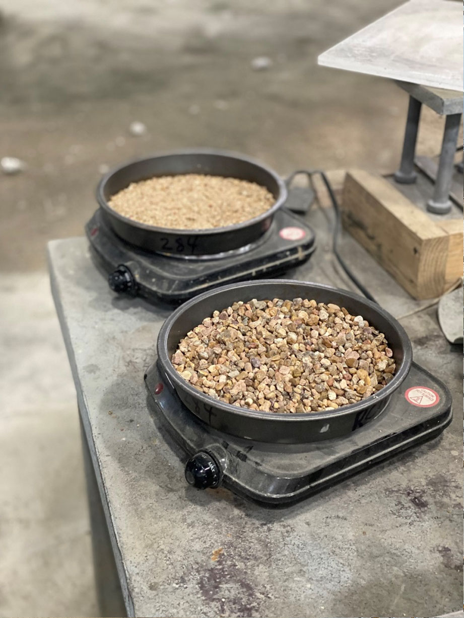
Before production can begin, it is important that the correct materials are selected for the structure. The aggregates and materials that go into the concrete such as sand and rock will be inspected upon arrival and before a batch mix is created. It is also important to know if any moisture is within the aggregates, this can impact the consistency of the concrete. Additives may also be necessary and useful when creating the proper batch mix. Additives can help the concrete’s flowability along will helping the concrete’s curing and strength.

When inspecting materials, the cement should first comply with ASTM C150 or “Standard Specification for Portland Cement” and should conform to Type I/II Blended. There should be moderate hydration and moderate resistance to sulfates. The materials will also be certified through a mill test report for each shipment or batch of cements. Type F Fly Ash will be used and should comply with ASTM C618. Admixtures should also comply with ASTM C494 and ASTM C1017. Aggregates including rock and sand should also conform to the requirements of ASTM C33, or the “Standard Specification for Concrete Aggregates.” Additionally, the aggregates will be evaluated, and documentation will be kept on file at the plant for potential harmful expansion from alkali reactivity. 


INITIAL STAGE


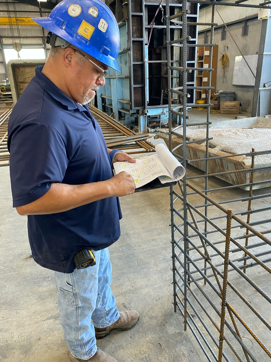
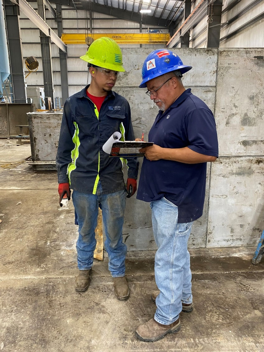
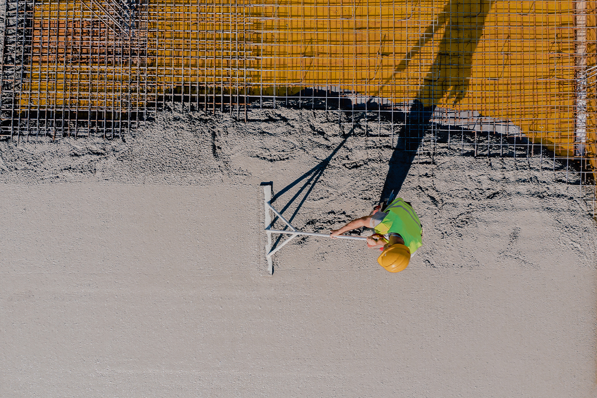
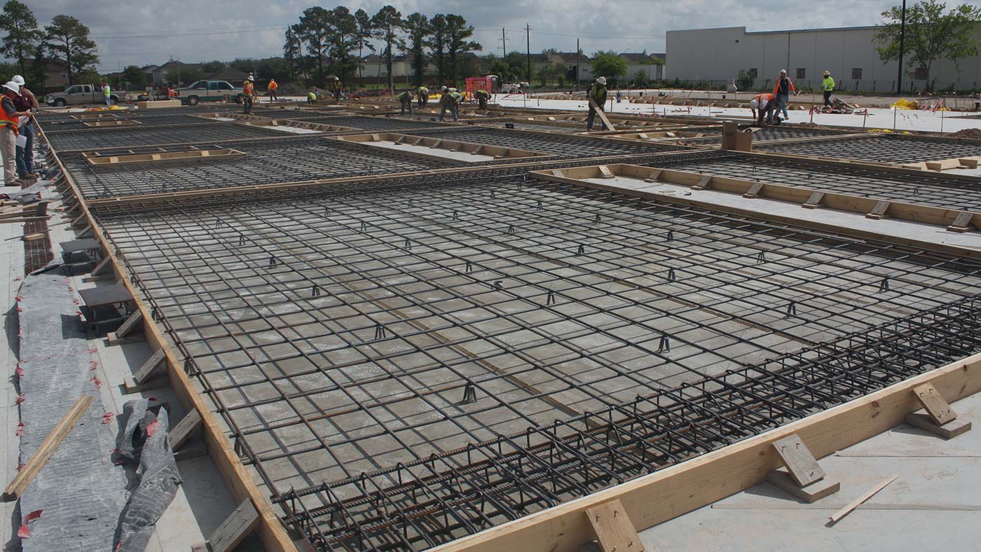
Building the rebar cage is the first phase of constructing any precast structure. It provides the strength and integrity for the structure. Before construction of the product can begin, the drawings for the structure must first be approved. Details for the rebar will also be supplied regarding appropriate sizing and spacing for the structure. Once the drawings have been verified, the first day of construction will be scheduled. The rebar cage will be constructed one day prior to the structure being poured. The measurements of the rebar cage will be checked throughout the entirety of its construction by the rebar crew. Once the construction of the cage is complete, QC will check the dimensions of the structure to ensure that they match the drawings of the product.


QC CHECKS REBAR

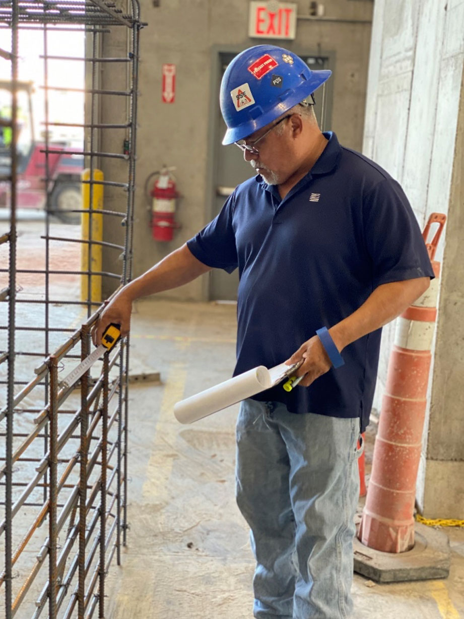
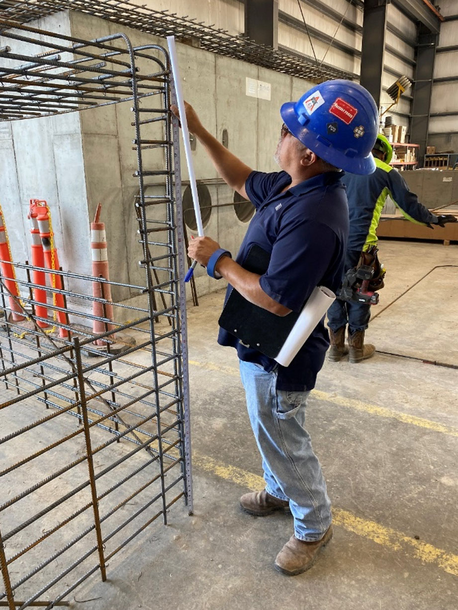
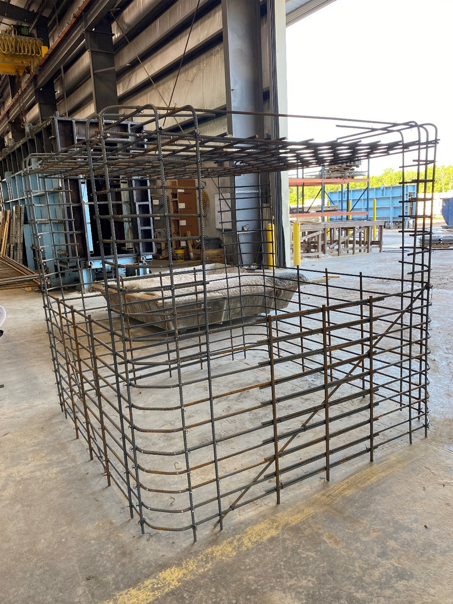
The QC team will check and measure spacing between the rebar, along with measuring the height and width of the rebar cage to ensure that all measurements are correct. Once this step is complete, the pre-pour set up and pre-pour check can take place.


QC CHECKS PRE-POUR SET UP

When the pre-pour set up is ready, QC will then check the set up before the structure is poured. They will check all dimensions of the mold including walls, terminators, openings, joints, and floor and top levelness. QC will also communicate with the Batch Plant Operator to verify the appropriate mix design for the structure. 


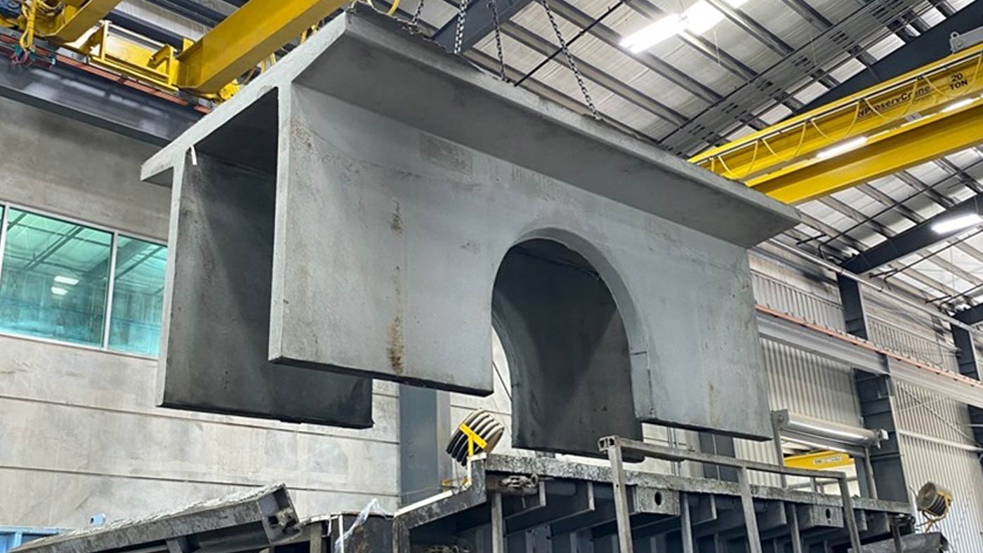
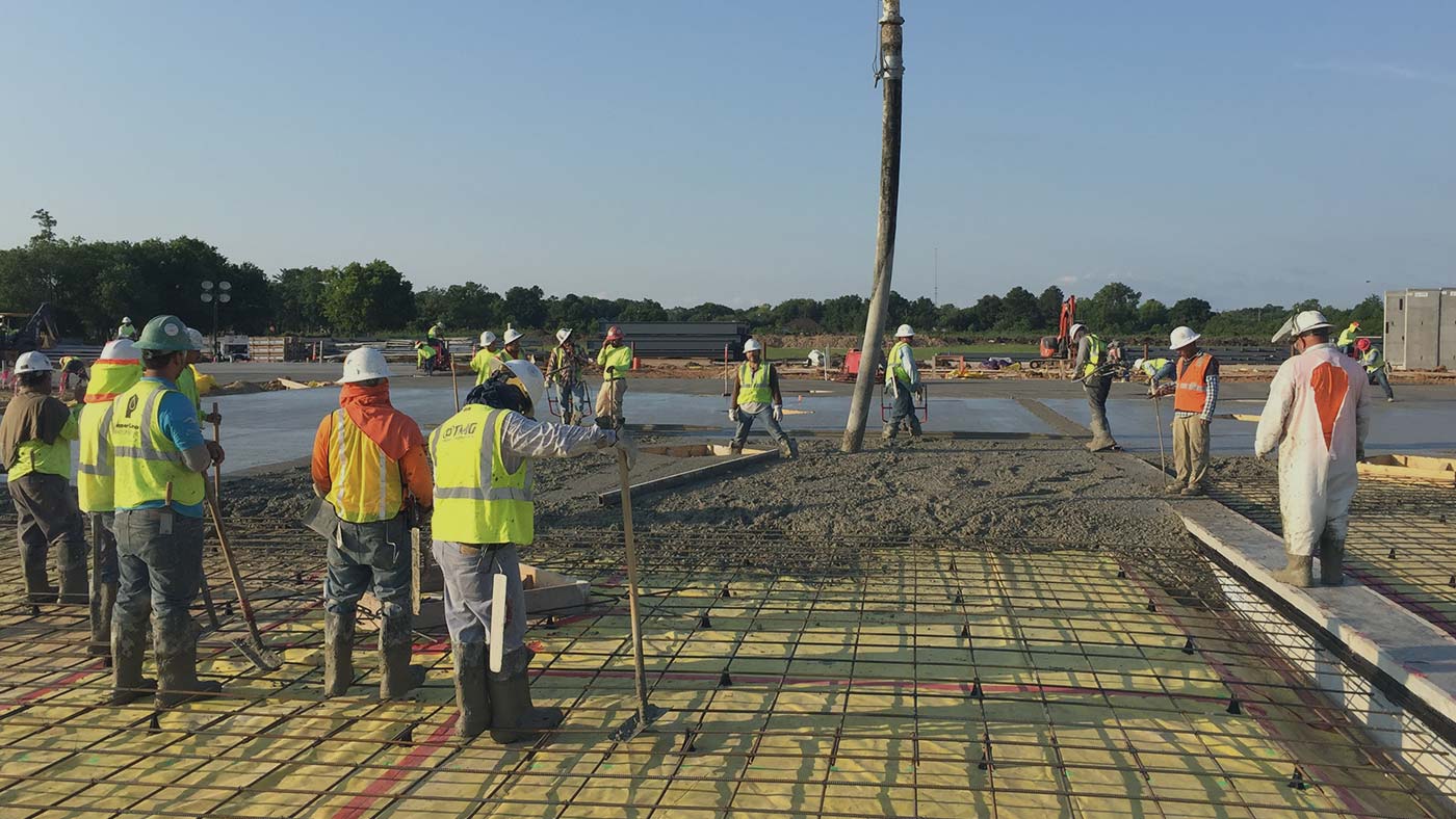
THE STRUCTURE IS READY TO BE POURED

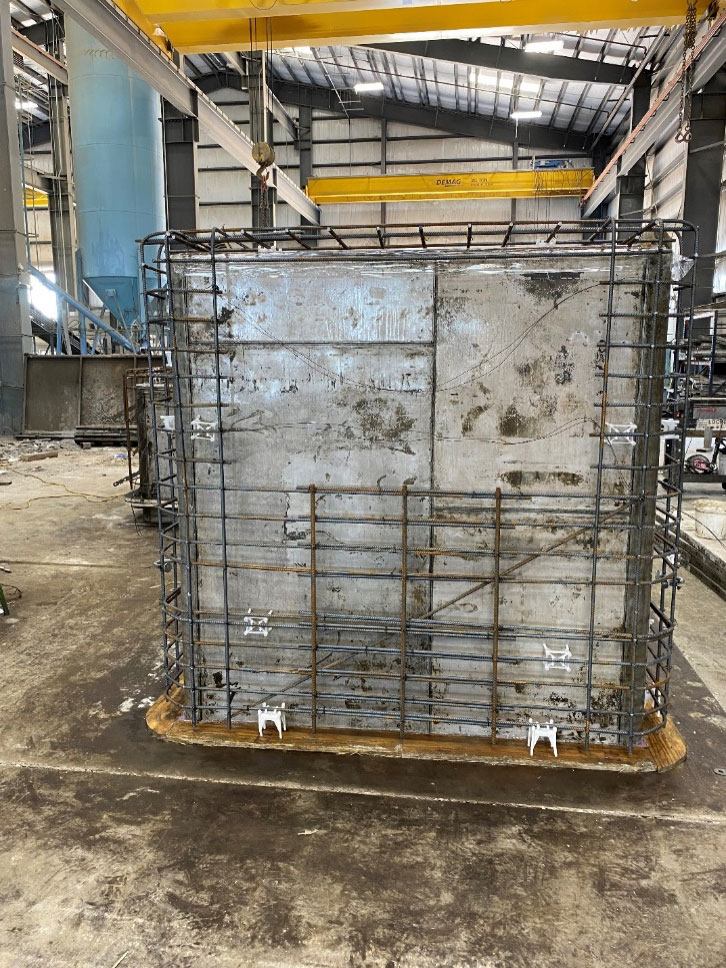
Once the pre-pour set up and QC checks are complete, the rebar cage can be put in place with the mold. The structure is now ready to be poured. 


QC TESTING

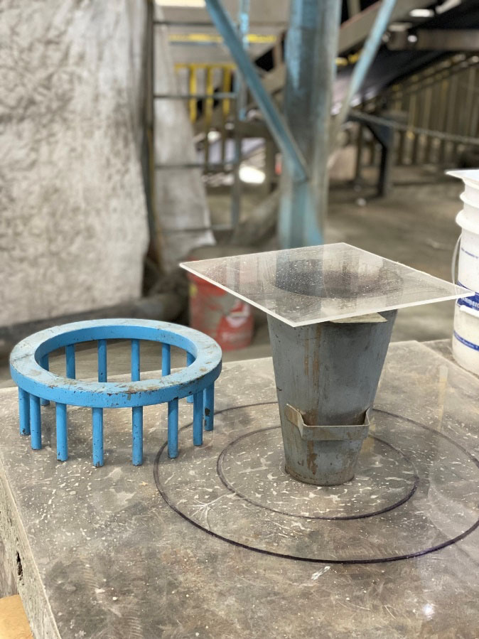
When the batch mix for the structure has been prepared, QC will take samples from the concrete batch and conduct testing. The main purpose of taking samples is to learn the strength that the structure will have along with the consistency of the concrete. NCC or normal cement concrete and SCC or self-consolidating concrete are commonly used in the precast industry. The main difference between the two, is that SCC allows for increased consolidation, better distribution to congested areas, and an improved overall finish for the structure. QC will conduct “spread tests” which assess how easily the concrete flows. To conduct this test, the concrete will be poured into a cone. The cone will then be lifted, allowing the concrete to expand. Once it has expanded, QC will measure the diameter of the spread. The spread should measure between 22-28 inches. 


TEMPERATURE TESTING


A certified quality control technician will also take the ambient temperature, followed by taking the temperature of the concrete.  


UNIT WEIGHT & VOLUMETRIC TESTING

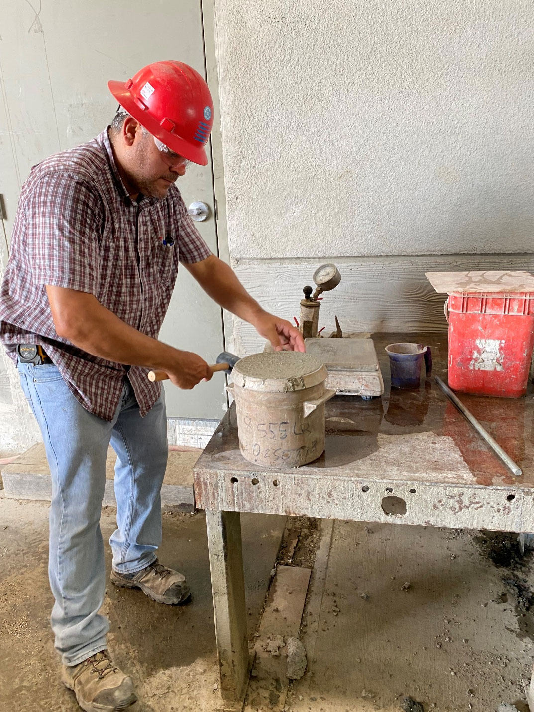
QC will also perform unit measure and volumetric testing. These tests work together to measure the weight of one cubic foot of the concrete and ensure that the batch is consistent with the mix design. The unit measure test consists of pouring the concrete into a unit weight bucket, and then it is malleted to ensure that the concrete is evenly distributed in the bucket. 

Next, the top will be striked off to remove any excess concrete and the bucket will be placed on the scale. The unit weight is determined by subtracting the weight of the empty bucket from the weight of the concrete and bucket together. After this, the volumetric test can be calculated by taking the unit weight measurement and dividing it by the volume of the empty bucket. This will give you the weight of the concrete per cubic foot. For example, our concrete typically weighs around 150 lbs per cubic foot. 


AIR ENTRAINMENT TEST

Measuring entrained air is also an important function of QC. Without air, the concrete does not have room to expand when exposed to freezing temperatures and could potentially put the structure at risk for cracking. 

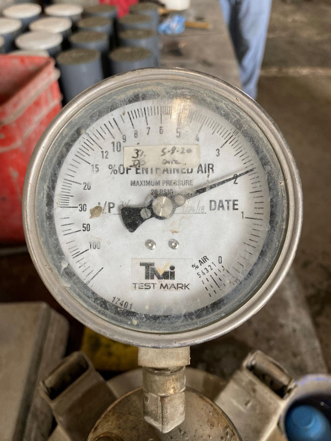
An air entrainment meter can be used to take this measurement.  


COMPRESSIVE STRENGTH TESTING

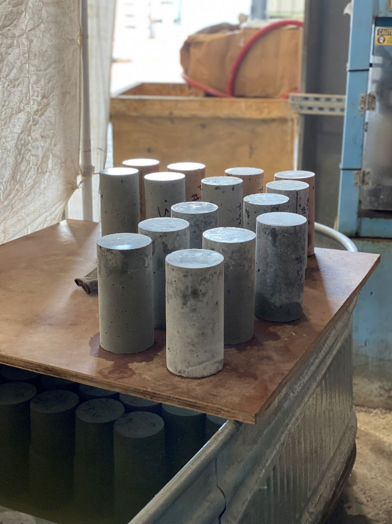
Structures can have different pounds per square inch (PSI) level requirements. To know the strength of the product, samples will be taken of the concrete to test its strength. Testing is conducted after the first day, on the 7th day, 14th, and finally on the 28th day when the concrete has reached its full strength. 

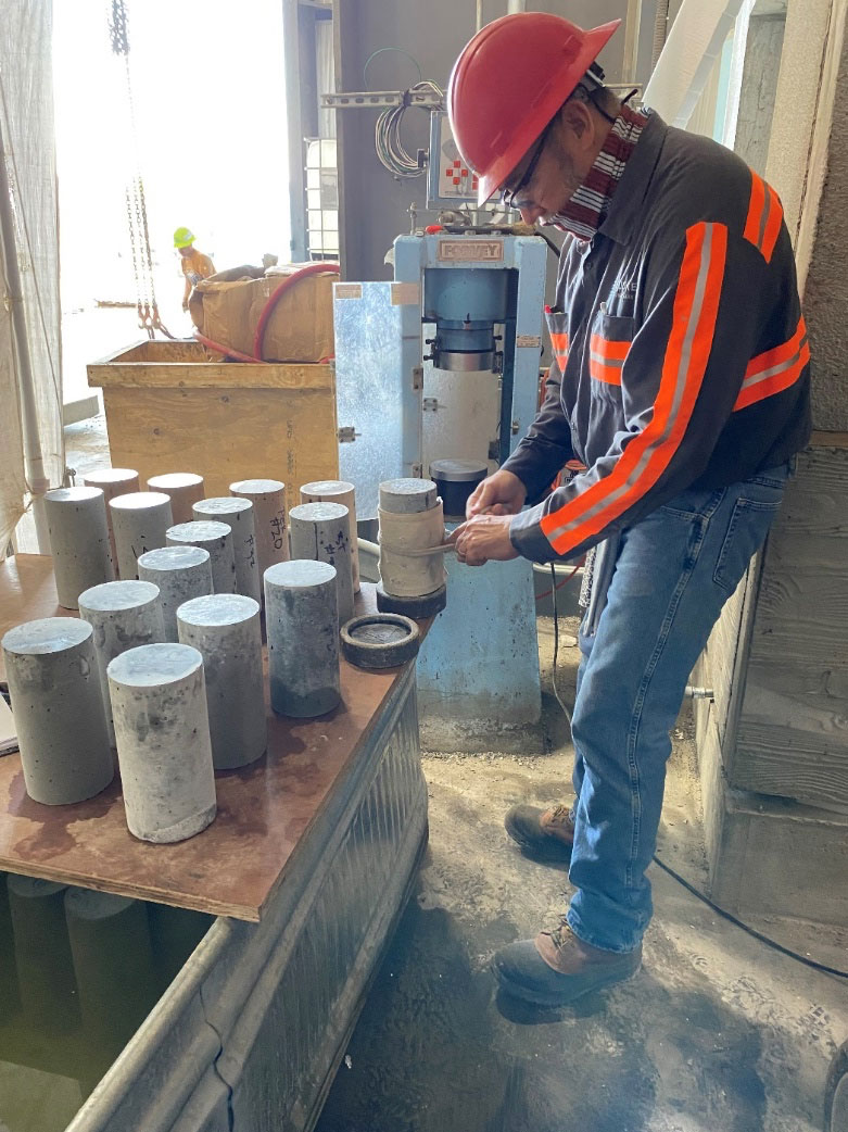
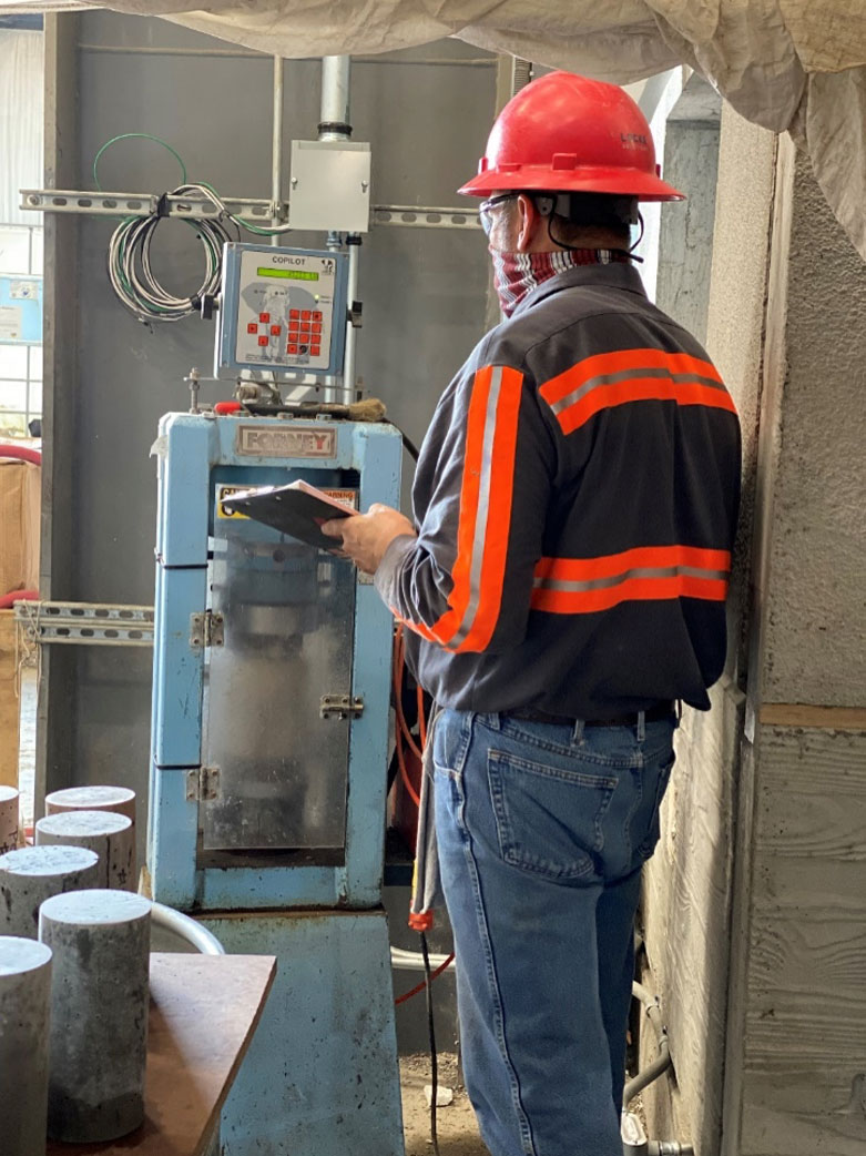
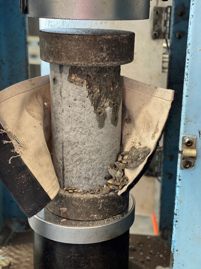
The concrete cylinder will be placed in a concrete compression machine. The machine will compress down on the cylinder until it pops and measure the PSI that was needed to break the cylinder. This information is recorded by QC and will be supplied to the customer so that they know the strength of their product. 


POST -POUR QC CHECK

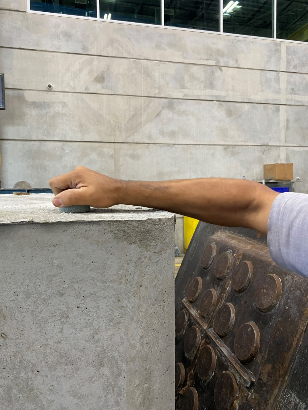
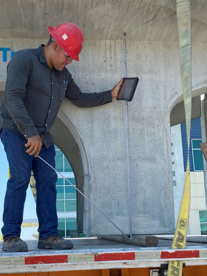
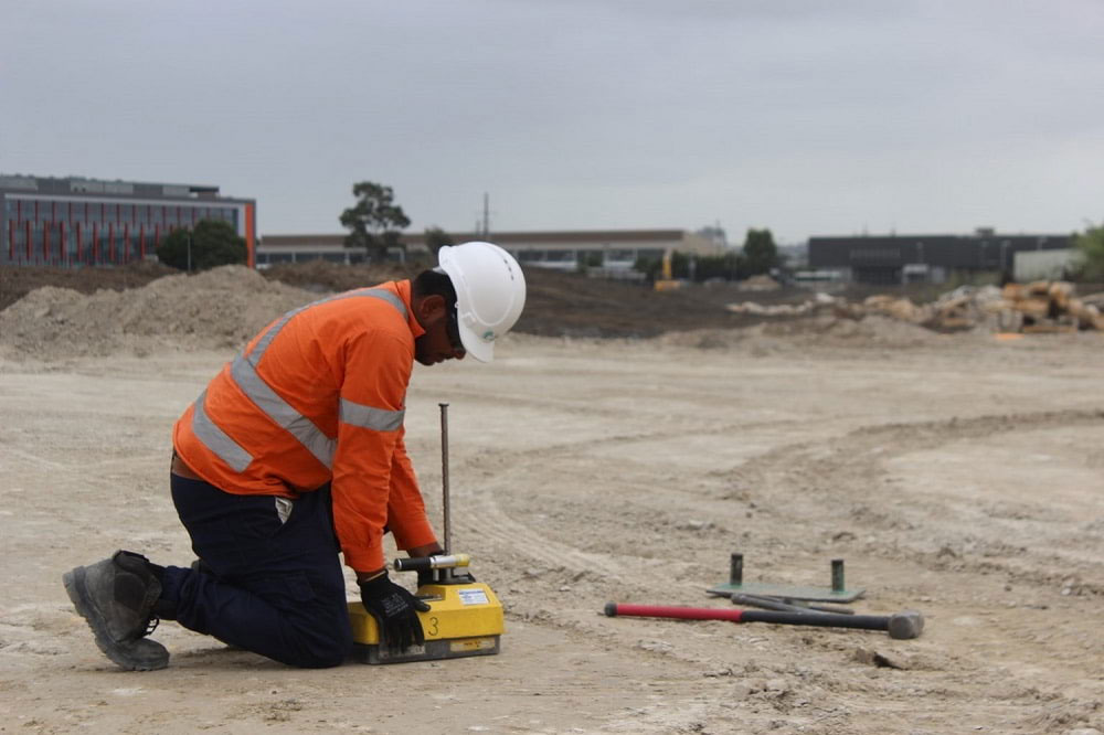
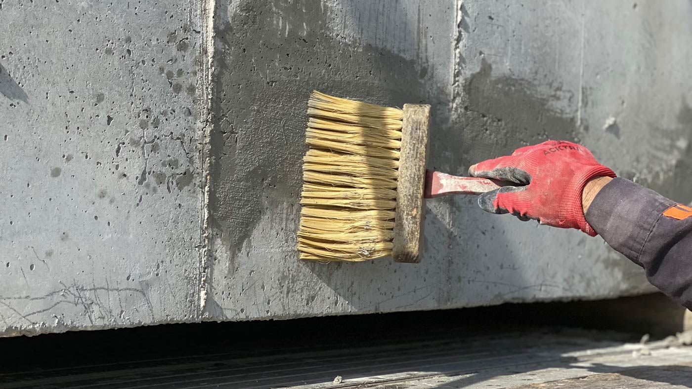
Before stripping a structure, QC will check the PSI level to ensure that it is strong enough to remove from the mold. It is important that the surface is smooth and flat to ensure an accurate reading. 

Shown here is a Schmidt hammer measuring the PSI level of this pull box.

When performing this test, the PSI levels should be measured near the location of the anchors, since these areas will encounter the most tension when being lifted from the mold. 

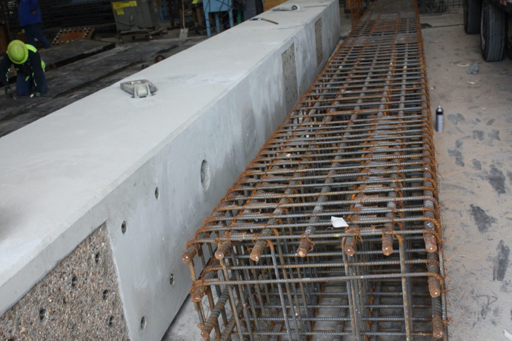
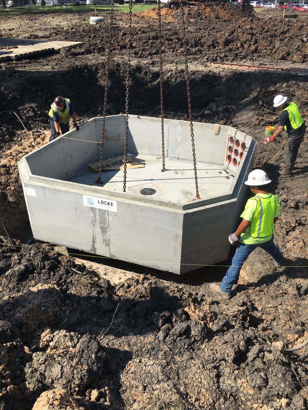
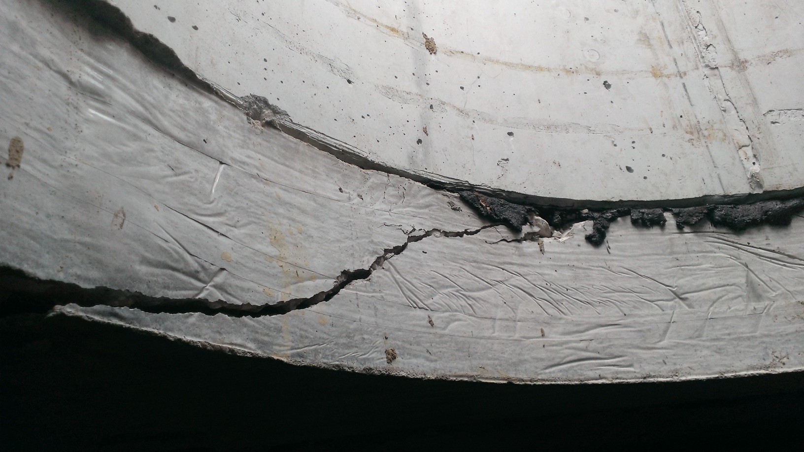
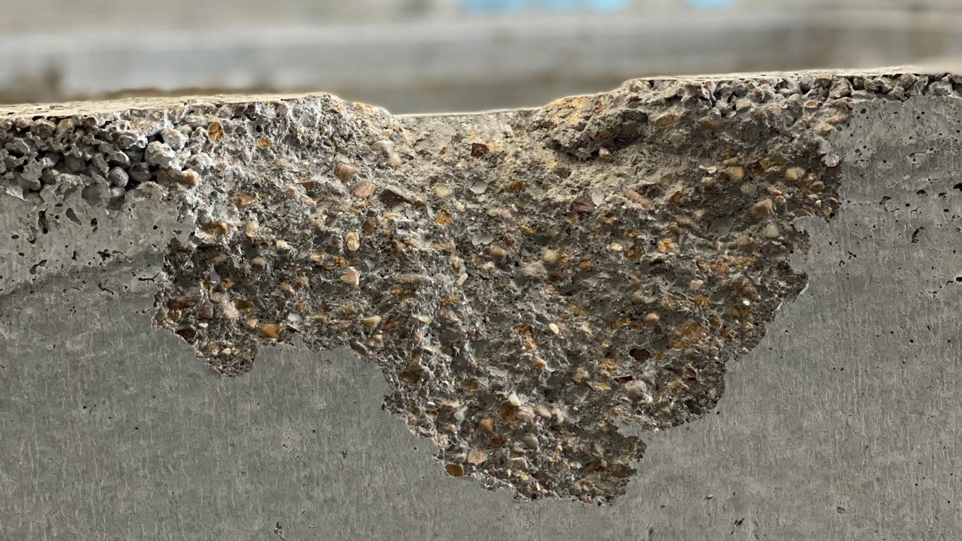
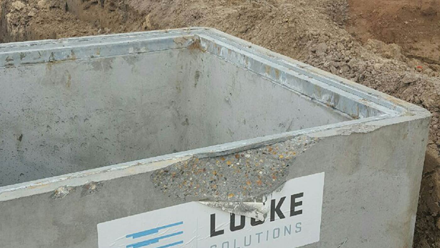
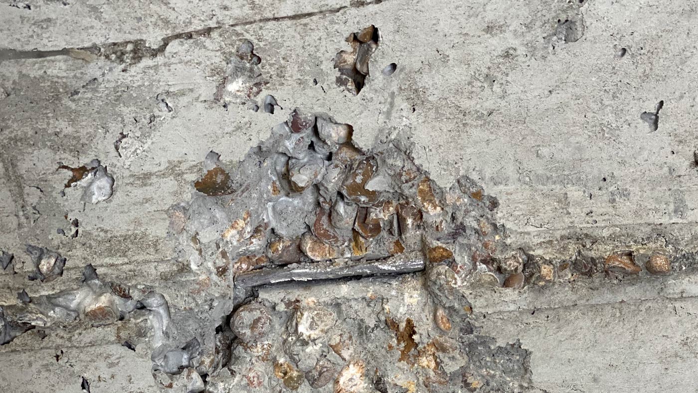
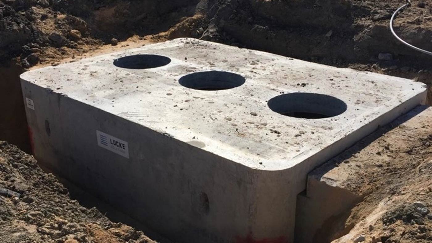
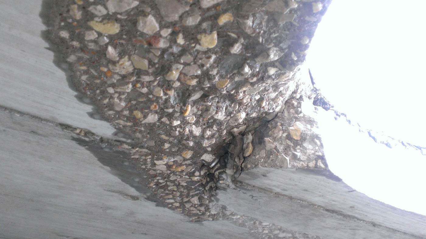
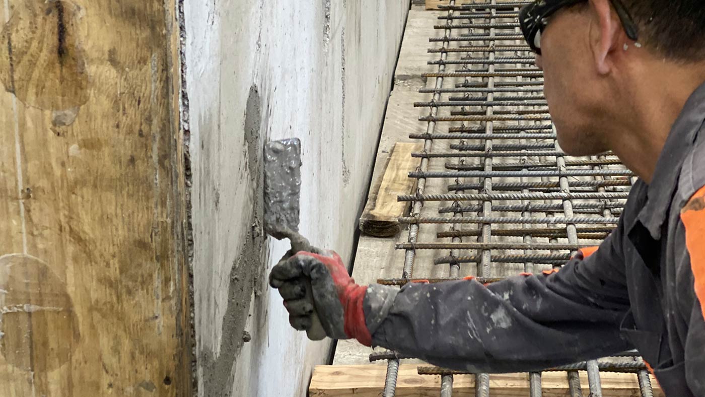
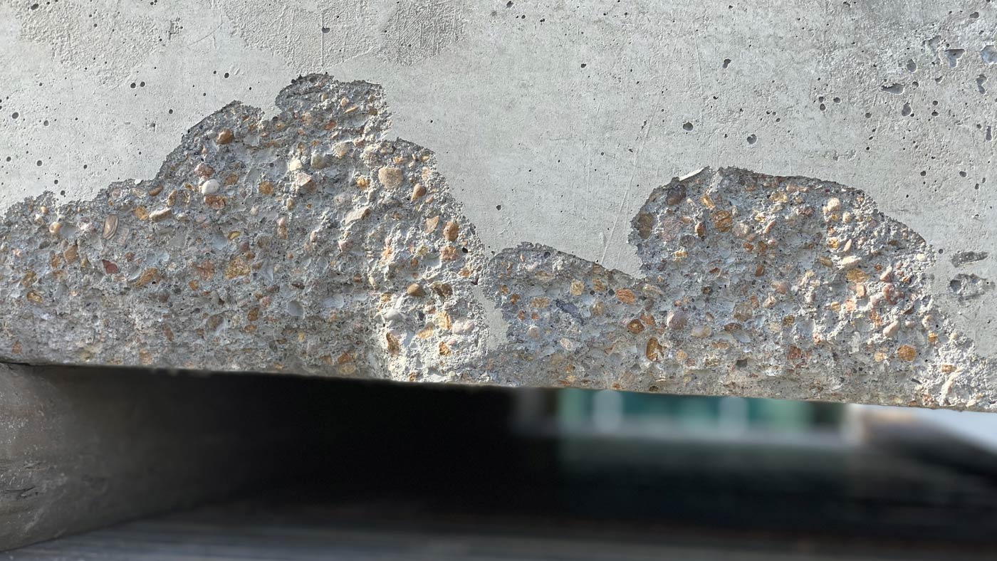
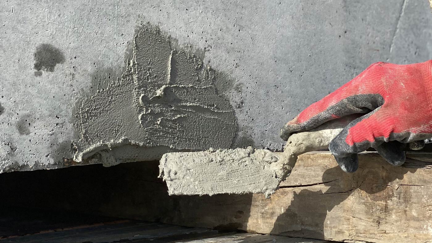
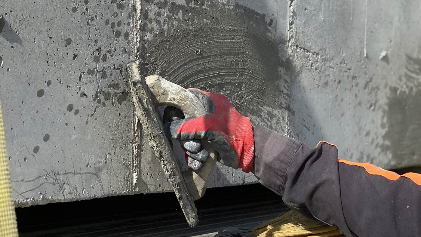
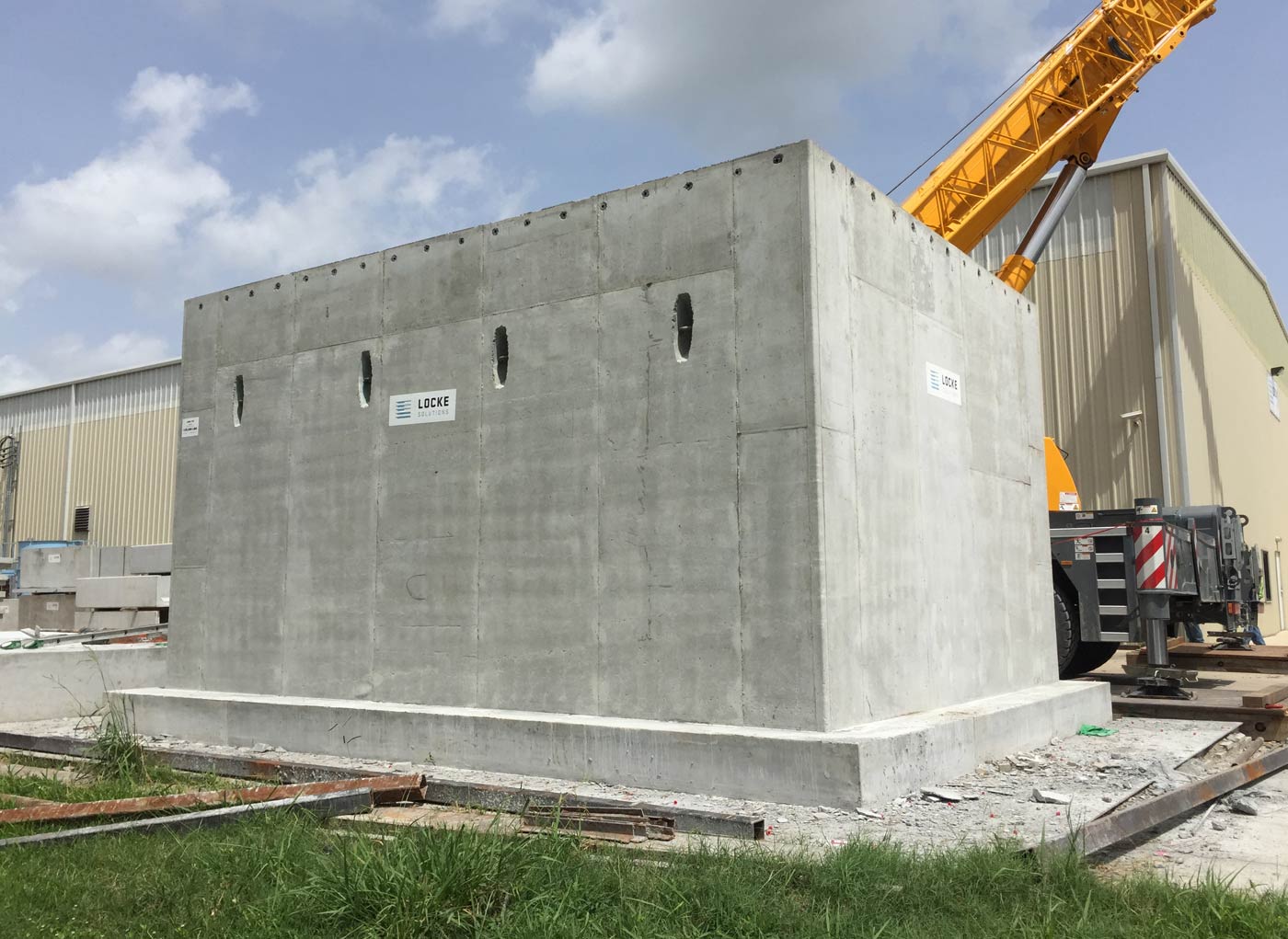
When the product is stripped from the mold, QC will conduct a post-pour quality check. The QC team will verify that the dimensions of the structure are correct by measuring and checking all walls, openings, terminators, joints, and floor and top levelness. They will also inspect for any cracking, chipping, or spalls. If any of these are present, QC will order repairs for the structure. 

If all dimensions of the structure are correct and no repairs are needed, QC will sign off on the structure and a shipping date will then be determined. 
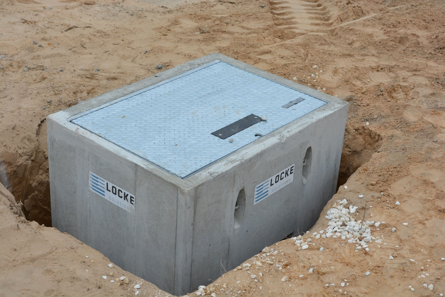
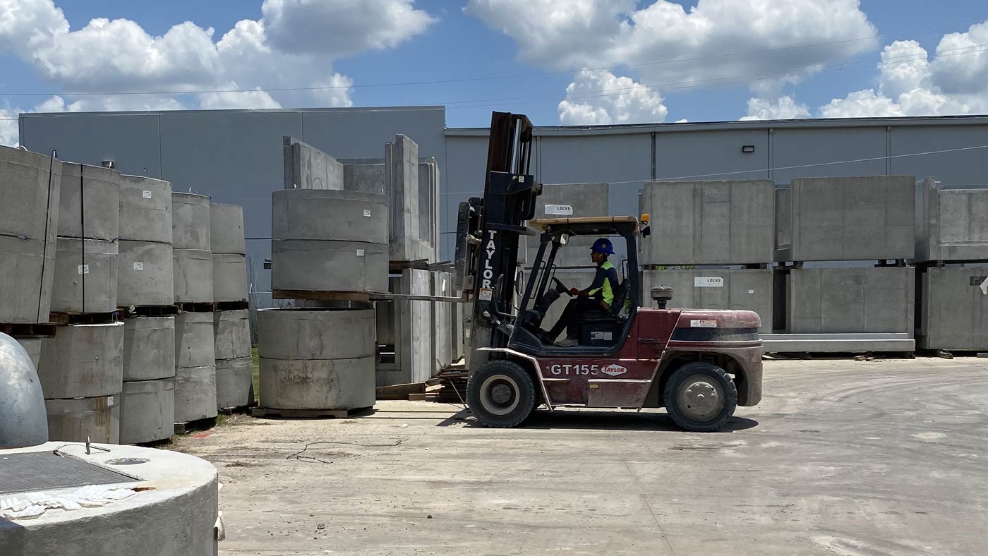
 

READY FOR SHIPMENT

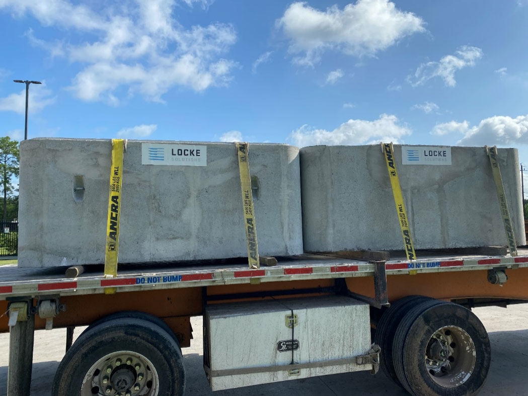
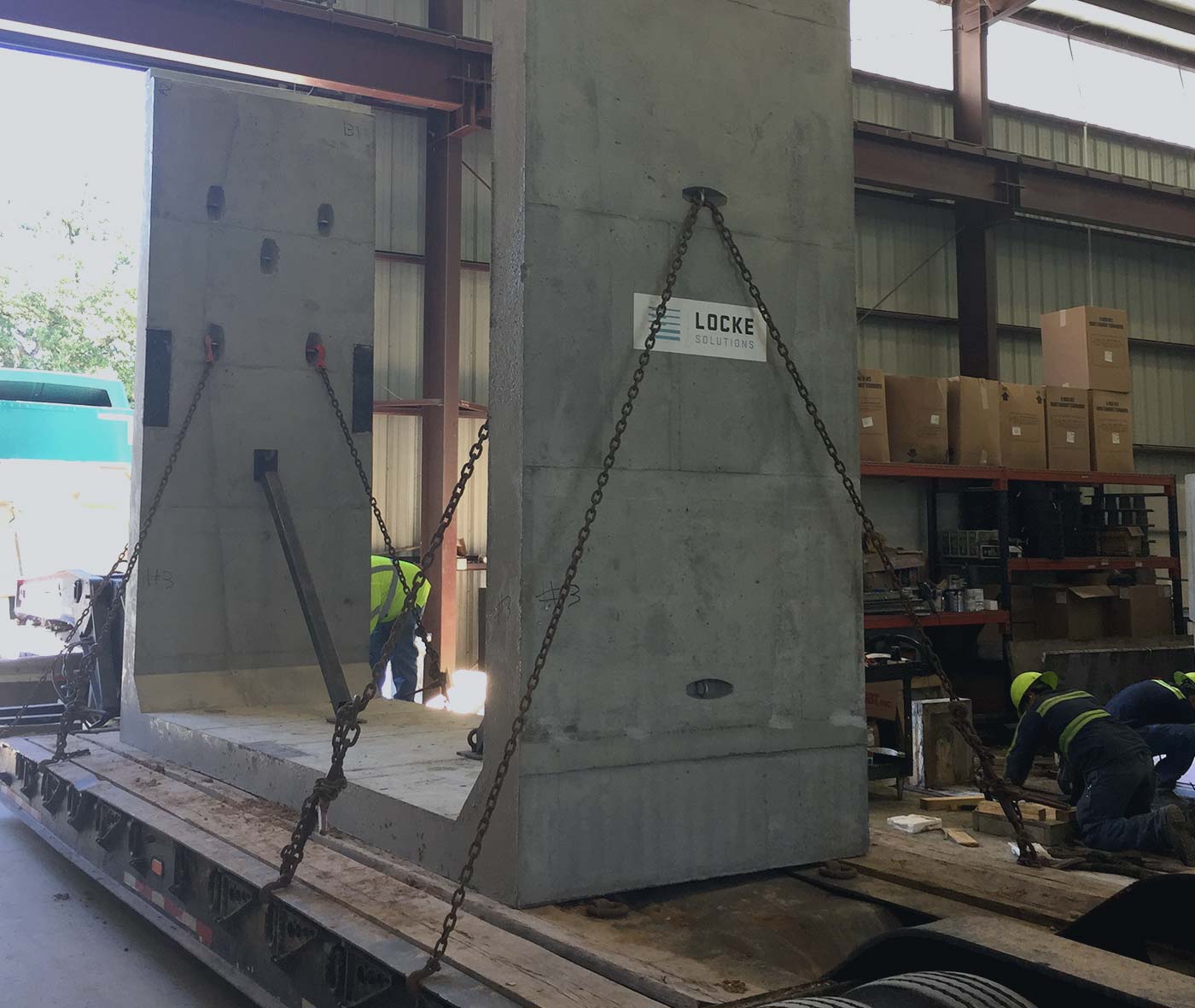
When transportation arrives, the product will be verified and signed off by the loading person and QC. Final checks will be conducted by QC to ensure that the structure drawings and line items match. They will also check again to ensure that no repairs are needed for the structure.

Once final checks are made by QC, the transportation driver will strategically secure the products and deliver them to the jobsite.


QC IMPORTANCE

Consistently producing quality products for customers should always be a priority. Customer’s value high quality standards and they recognize those who make efforts to meet and their needs. Checking and conducting thorough testing for each individual product enables the precaster to ensure that the product will meet and exceed customer expectations. This, however, can only be accomplished with a knowledgeable and highly detail-oriented QC team. 


Stay tuned for our next article.

We hope this article was helpful. Please send in your questions to info@lockesolutions.com and we would be happy to help answer them.

achive.php: you are in the loop
slug: tips-for-preparing-subgrade-and-installation-of-precast-concrete-products
post_type:post

Image sourced from ADE Consulting Group

The strength and integrity of a structure is important. Some will argue that the foundation that supports the structure is even more important. Let’s dig deeper into everything about the subgrade.

PREPARATIONS FOR THE SUBGRADE

First off, what is the subgrade? The subgrade is what lies below the grade or ground level, providing a strong foundation for the structure. The subgrade can consist of different materials and can be of different depths. It is usually comprised of rock, sand, cement, or limestone. The depths of a subgrade can range depending on the contents of the soil and the size of the structure. For example, a smaller structure may only require a depth of a 6-inch subgrade whereas a larger structure may require a deeper subgrade that is closer to 20-30 feet. Larger structures may also require several different layers within the subgrade. These layers can consist of rock, sand, stabilized sand, cement, lime cement, limestone, and manufactured aggregates. Before the subgrade is prepared, there are a few steps that must first take place. The Engineer of Record does not only design the precast structure, but they will also create plans for the subgrade. When preparations for the subgrade are ready to begin, the customer will first contact a geotech company to conduct soil testing for the location of the structure. The Engineer of Record will give the plans for the structure to the Soil Engineer before they begin testing the soil. The testing will provide information about what properties the soil contains. Soil can be comprised of sand, clay, or rock. To conduct soil testing, the soil engineer will core the ground. The Geotech Engineer will make the decision on how far down to drill along with how many different places coring should take place. How deep to drill is also dependent on the structure’s size, weight, and the function that it will serve. Once the coring is complete and the soil sample has been tested, a report will be created and provided to the customer. The customer will then share the report with the Engineer of Record, and the Engineer of Record will now move forward with creating the plans for the subgrade. 


EQUIPMENT USED

Trackhoes are commonly used to excavate the ground for a subgrade. 


The excavated ground will then be loaded into the back of a truck. If the dirt is contaminated, it will be disposed of. If it is clean and free of contaminates, it can be used in a variety of ways. If the job site has no use for the dirt, it can also be taken to other organizations such as schools, farms, or parks for landscaping or other projects that may be useful. If there is no need for the dirt, it will be transported to a landfill for disposal. 


When the subgrade is at the correct depth and all appropriate subgrade materials have been added, the subgrade will be compacted using a compactor machine that rolls and compacts the ground. It is critical that the subgrade is evenly compacted providing the ultimate strength for the structure. 

Imaged sourced from NMC CAT

A Motor Grader is another type of machinery that can also be used to flatten and compact grading. 

Image sourced from Water Pros

Water trucks and tanker trucks may also be used to deliver water and other materials that will assist with subgrade compaction. 

Reclamation machine. Image sourced from ASPHALTPRO

Reclaiming machines are also used to penetrate and mix the base with different pavement layers to create a level subgrade for the structure to sit. 


COMMON TYPES OF EXCAVATIONS


Shoring is a type of excavation that is done by installing large steel plates with steel I beams in between. It is designed to hold the earth and prevent the ground from caving in. Shoring plans must always be created by an engineer because it is a lengthy and technical process. There is also more risk involved. The shoring must also be removed once the precast structure goes in place. This form of excavation can be more extensive and can be a greater expense. 

Another form of excavation is a step back excavation, also known as stepping or benching. The ground is excavated to create horizontal steps at an incline that lead out of the excavation site. This type of excavation is also designed to prevent any caving in of the ground. One thing to note is that stepping puts you further from the center of the excavation, necessitating larger cranes. The location and size of the job site should also be considered when using step back excavation. This type of excavation can sometimes require significant space. This form of excavation usually involves fewer safety risks and has lower costs when compared to shoring.


WEATHER CONSIDERATIONS


Weather, particularly rain is always a factor that must be considered when excavating. If it rains while the ground is excavated, water may need to be pumped out until the subgrade is dry. Dewatering pipes or well-points can also be installed to facilitate drainage from the excavation site. 

SETTING PRECAST IN PLACE

It is important to ensure that the subgrade has been compacted correctly and is strong enough to hold the structure. Using a Dynamic Cone Penetrometer is a useful way to measure and check the compaction level of the subgrade.

Image sourced from ADE Consulting Group


Once the subgrade is compacted and inspected, the structure can be set into place. When this occurs, backfilling with the appropriate contents that have been approved by the Soil Engineer can begin. Backfilling material can consist of sand, rock, limestone, cement, and flowable concrete. This stabilizes the soil and provides it with more strength. 

IMPORTANT TAKEAWAYS 

The subgrade is a critical component of a precast structure’s longevity and performance. Following the correct protocol will ensure that the subgrade has been properly prepared for the structure. Here are a few steps to remember when developing a subgrade:

  • The Soil Engineer should test and identify soil properties which will determine the best components needed for the subgrade along with the correct backfill materials
  • The Engineer of Record should design an appropriate subgrade for the structure
  • Backhoes, trucks, compacting machines, and cranes with adequate reach will be needed 
  • Choosing which form of excavation to implement should always be specific to the job and should always account for the safety of all who are involved
  • Weather should always be considered, and the subgrade should be inspected after rain occurs before offloading the structure into place
  • An even compaction is key to giving the subgrade ultimate strength 


Stay tuned for our next article.

We hope this article was helpful. Please send in your questions to info@lockesolutions.com and we would be happy to help answer them.

achive.php: you are in the loop
slug: understanding-chips-and-cracked-precast
post_type:post


There are occasions when cracks, chips, or spalls occur in concrete. When these forms of damage occur to a structure, it is important to understand the severity of the damage so you can use proper procedures to repair the concrete. In this article, we talk about the differences in these defects, what some of the common causes are, and what to look for when assessing how to repair a precast concrete structure.

CHIPPING

Chipping is often the result of impact on the concrete, and they typically occur on the edges or corners of a structure. Chips are considered to be smaller areas of breakage on a concrete structure that can be as deep as 1 inch and as wide as 8 inches. Chips are usually seen as a cosmetic issue and normally do not impact the structural integrity of the structure. During the precast manufacturing process, chips can occur when structures are removed roughly from their molds or are improperly handled or stored.  On the jobsite, chips typically occur from improper handling of the product such wrapping chains around the structure and dragging it or unintentional collisions with other structures during the installation process. 


SPALLS

Spalls are similar to chips but typically occur on the edge of a concrete surface.  As is the case with chips, spalls are typically cosmetic in nature, but can range in size from small to large areas of the concrete edge. Like chips, they usually occur from impact or pressure applied to the edge of a concrete surface. Spalls that expose structural reinforcement are considered more severe and repairing these structures correctly is critical for the long-term life of the product. The most common cause of spalled edges occurs during handling and storage. Dunnage is typically used to support precast structures and allow access for forklift access underneath. Imperfections along the edges of the concrete surface can lead to a “point load” effect when the concrete is placed on dunnage or when forks are picking up the structure. This pressure concentrated in a small area along the edge of the surface can easily lead to a spalled edge. A great way to reduce the chances of spalling in these situations, is by creating a rounded or chamfered edge where the forks and dunnage will be supporting the structure.


CRACKS

Cracks can vary in size and depth and require more experience to evaluate. Concrete is inherently weak in tension and is designed with the expectation of it cracking up to the point where the steel reinforcement is located. Cracks can range from being minor and not require any treatment at all, to catastrophic and requiring major repairs to maintain the structural integrity of a product.

One type of minor cracking is surface cracks often found on the top surface of concrete structures. They are usually small in size, run across an unformed surface of a structure, and typically occur when the curing process is poor. Sometimes these cracks are called temperature or shrinkage cracks. These cracks occur when the surface dries quickly due to heat or wind and no controls are used to cure the surface at a slower rate maintaining moisture while the cement hydrates. These types of cracks may also present themselves if there is a high water to cement ratio in concrete mix design.

Another type of crack is called a re-entrant corner crack. These are very common and are due to stress on the corners of a structure. This usually occurs with structures that have squared off edges and the cracks will normally present themselves once the structure has cured. One way to minimize this problem is to create structures with rounded edges instead of squared off edges. Rounder edges provide more strength to the structure and can greatly help to reduce these types of cracks.

More severe cracking can occur on structures not properly handled or stored.  For prefabricated concrete structures, they should rest on level surfaces and on dunnage that has been properly placed based on the design of the structure. Concrete is heavy and instances with the weight not properly distributed across the dunnage can lead to excessive stress on the structure. If it has not been designed for those stresses, there is a potential for it to develop stress cracks. Storage of larger precast sections should be evaluated and designed by an engineer.


ADDRESSING THE CAUSE & PREVENTATIVE MEASURES

Before a structure is repaired, it is important to understand the cause of the damage and what the final use of the product will be. For any structures with major damage, an engineer should assess the damage and evaluate the structural integrity before moving forward with any repair. This ensures that the correct actions will be taken to properly repair the structure. In addition, industry best practice is to prepare a damage assessment report to dig into root causes in order to learn and prevent damage of future structures. 


HANDLING PRODUCTS

One of the most common ways for precast products to get damaged is due to improper handling. The product should always be carefully lifted and stripped from its casting mold after reaching the design stripping compressive strength. Normally, precast structures are not at full 28 day design strength when being demolded, but there should be a stripping strength designated and the concrete should be tested to ensure it is as this designated stripping strength. Molds should also be checked to ensure that they are not causing any damage to the structure and working properly. If molds are not properly coated with a form release agent, it may create problems during the stripping process and allow binding up when the product is being removed. 


MAKING COSMETIC CONCRETE REPAIRS

“Patching” is usually the term that is used when performing cosmetic repairs to concrete structures. Patch mixtures can be cement based or have additional mineral additives added to the mix. They can also be comprised of an epoxy mortar, epoxy cement, or a polymer mixture. When repairing a damaged structure, it is first important to understand the severity of the damage to the structure. Qualified and competent personnel should assess the damage and if necessary, a qualified engineer should be involved for any potential structural damage. 


COSMETIC REPAIRS ON PRECAST CONCRETE

In handling cosmetic repairs, the surface of the structure should first be prepared properly. Prepping the surface before the application of the repair material is one of the most important steps. The surface should be clean and free of any debris. Weather conditions should also be taken into consideration, as colder temperature will slow the patch material from curing. 

Once the surface the has been prepped and the patch mixture is ready, water or a bonding agent may be applied to the site with a brush. This adds moisture to the area. Once this takes place, a trowel can be used to apply the patch mixture. It is important that the mixture is applied evenly across the surface of the structure. 

Once the mixture has been evenly distributed, it can be smoothed over with sweeping motions.

Once the patch mixture has been evenly distributed, a brush will be used to smooth over the surface. 


FINAL THOUGHTS

It is important that when cracks, spalls, or chips damage a structure, the severity of the damage is assessed. Repairs can be costly, especially with structures that receive significant damage. Structures that receive extensive structural damage may even be required to be replaced. It is critical that the product is properly inspected when damage does occur to ensure that with repairs, it will still be structurally sound. It is also important to understand what the cause of the damage was, so that changes and preventative actions can take place for future structures. Understanding the extent and cause of the damage along with proper surface preparations, a compatible patch mix, and proper application are key to a successful repair. 


Stay tuned for our next article.

We hope this article was helpful. Please send in your questions to info@lockesolutions.com and we would be happy to help answer them.

achive.php: you are in the loop
slug: precast-vs-cast-in-place
post_type:post

Understanding the differences between precast concrete and cast-in-place concrete is often misunderstood. The primary difference is the method of construction, but the finished product should be nearly the same or identical.  There are several key differences between these two types of construction methods. Recognizing and understanding their differences will help you to choose the method that will be best for your project’s specific needs. This article will be geared more towards the construction of underground concrete structures. 

What does Cast-in-Place mean?

The term “Cast-in-Place” is used for the construction method of placing concrete and curing on-site and is also sometimes referred to as in-situ casting or pour-in-place. “It’s the most prevalent form of concrete construction, which consists of creating a mold onsite primarily using wood or steel panels and placing concrete directly to the final position of the structure” explains Asher Kazmann. The concrete is normally transported in a ready-mix concrete truck to the job site in an unhardened state. Once on-site, the truck will place the concrete directly in the final position if it is able to get close enough to access it, otherwise, the concrete is placed in a pour bucket or into a concrete pump truck.  A pour bucket may be moved with a crane or excavator to its destination while a pump truck can pump the concrete through piping vertically or horizontally up to around 200 feet away. Common uses of the cast-in-place method include parking lots, road paving, and housing foundations. 

What does Precast mean?

Precast concrete structures are prefabricated and cured off-site.  Precast structures are fabricated in a similar fashion as cast-in-place structures, except they are fabricated prior to installation in a manufacturing plant.  Common structures precast include wall panels, trenches, staircases, septic tanks, grease traps, bridge beams, box culvert, and pipe.   


Installation Process for Cast-In-Place Construction Method

The process of concrete construction using the cast-in-place method is virtually the same for all underground concrete structures.  Here are the basics steps.

  1. Excavating, shoring, and prepping the subgrade.
  2. Fabrication and tying of the steel reinforcing rebar. Often this step is performed by a separate trade referred to as rodbusters and generally, the rebar is prefabricated offsite, where it is cut and bent to specifications.  The rodbusters will assemble and tie the rebar and place it in the proper position in the excavated area.
  3. Formwork is set in place around the structure. This is the wood or steel panels that are assembled to hold the fresh concrete in place long enough to harden.  This formwork can be fabricated by carpenters or purchased by companies such as Dayton Superior Symons Panels or EFCO Forms.
  4. At this point, there is usually an inspection required by a third-party firm to verify the proper spacing and clearances of the reinforcing steel relative to the formwork and check that the overall dimensions of the formwork are within tolerance of specifications.
  5. Once inspections have been cleared, the concrete can be placed. It is important to confirm the formwork has been braced properly to withstand the hydrostatic pressure of the fresh concrete to prevent any movement of the forms or worse, a “blowout” of the formwork.  Also, a third-party inspection firm will typically take concrete samples during the concrete placement for future verification of concrete strengths and specifications.
  6. After placement of the concrete, it will need anywhere from 3 to 28 days to cure, depending on the concrete curing specifications and strength requirements. The strength of the concrete is often confirmed by performing proof load compressive strength tests on sample concrete cylinders. 
  7. Once curing requirements are met and the concrete has reached the required strength, the formwork can then be removed.
  8. Any required patching or clean-up can be performed at this point and a final inspection is done to confirm the dimensions of the concrete structure still meet tolerances.
  9. Finally, backfilling can take place.  The backfilling process typically takes place in several layers of backfill anywhere from 6” to 18” at a time while compacting each layer during the process.


Installation Process for Precast Concrete Construction Method

The process of concrete construction using precast concrete structures is similar to cast-in-place with the exception that many of the steps are done offsite.  Here are the basics steps.

  1. Excavating, shoring, and prepping the subgrade.
  2. Setting the precast concrete structure with an excavator or crane to the final position.  More information about safe offloading of precast structures can be found here (https://lockesolutions.com/safe-methods-for-offloading-handling-precast/). 
  3. With structures having multiple sections, joint sealant or grout is applied between sections to ensure a proper seal.  More information on typical joint sealants and installation can be found here (https://lockesolutions.com/precast-concrete-joint-sealants/).  
  4. Lastly, because the precast structure is already fully cured to design strength, backfilling can take place immediately.  The backfilling process typically takes place in several layers of backfill anywhere from 6” to 18” at a time while compacting each layer during the process.

Although the installation steps for precast concrete structures appear minimal, much of the fabrication process is being done offsite prior to installation.  Here are the typical steps in the manufacturing process that will not be seen on the job site.

  1. First, structural design analysis is performed to determine the necessary wall thicknesses, steel reinforcement size and spacing, and concrete strength to meet the project requirements.
  2. 3D models are created using CAD software.  These models are used to ensure no conflicts occur between all items cast into the structure.
  3. Production drawings are created from the models and detailed to show all necessary dimensions and specify proper lifting anchors, rebar placement, and other items such as cast-iron manhole rings that may be cast into the structure, for example.
  4. After approval of drawings, the steel reinforcing cage is fabricated by the precast manufacturer in advance.
  5. Quality Control technicians inspect the steel reinforcing cage for proper rebar size, spacing, and overall dimensions.  After inspection, the rebar cage is tagged to indicate its approval for production.
  6. Formwork is set up with steel, aluminum, or wood molds and inspected by Quality Control for cleanliness and proper dimensions and bracing.
  7. Next, the rebar cage is placed in the mold and spacers are added to ensure the rebar cage cannot shift in the mold during concrete placement.
  8. A pre-pour inspection is then performed by Quality Control to ensure all dimensions are still accurate and all rebar and items cast into the concrete are secured and in the correct position.  Once the inspection is complete, Quality Control then tags the mold to indicate its approval for concrete placement.
  9. Concrete is then batched in the manufacturing facility when needed and placed in the mold.
  10. During the concrete batching process, ACI-certified Quality Control technicians take a sample of the concrete and perform fresh concrete testing including temperature, air content, unit weight, and slump/spread tests.  If there are any deviations to the concrete results, a new batch of concrete is mixed.  Concrete sample cylinders are also taken during this process.
  11. After the concrete has cured and met strength requirements, the structure is de-molded from the formwork.  Quality Control then performs a post-post inspection to verify the dimensions of the structure are still within project tolerances.  During this process, the structure is labeled with information of the project, weight of the structure, and the date of production.  After the inspection is complete, Quality Control marks a sign of approval on the product, and it is then transferred to the laydown yard.
  12. Lastly, the precast manufacturer communicates with the contractor on the best delivery day and time and coordinates trucking to deliver the product to the job site.  More information on shipping best practices can be found here.
  13. Quality Control will perform compressive tests on the sample concrete cylinders and will retain these strength results to ensure the concrete has met the design strength requirements of the project.  The inspection reports, concrete cylinder tests, and material certifications are kept on file and available to the contractor if needed.


Advantages of Cast-In-Place

Cast-in-place is often the first choice when pouring foundations or slabs and it is often used when building large bridge column supports and roads. It can also be used when building walls and roofs.  Because precast structures are already fabricated prior to arriving at the job site, they are not as adaptable as casting a structure in-place. If a precast structure is brought to a job site and the dimensions are not compatible with the prepared area, then the precast structure may have to be modified or not used at all.  

In other situations, there may be concerns with having joints within a structure, such as a containment sump with hazardous liquids.  Precast structures often require multiple sections and joints within the structure.  Although there are many joint sealants and liners to provide a watertight structure, the cast-in-place method can oftentimes avoid this concern.

Precast concrete structures can also be challenging to handle because they can be heavy and extremely large. For this reason, cranes or larger equipment are typically needed to offload and place the precast structure into place. There is no need for this extra equipment in the cast-in-place construction process.

Casting structures in-place may also be more advantageous when working in a tight or restricted job site condition.  It can be difficult to lift and place a precast structure when overhead obstructions are present or working inside a building or parking garage.

Other inherent challenges with the precast concrete construction method are discussed in more detail here.


Advantages of Precast

Precast concrete does have its advantages. One being that it is made in a controlled environment. This means more quality controls are present with concrete batching, dimensions, and inspections.  Most precast manufacturers have certified technicians and engineers to monitor and aid the team during the production process.  

Another major advantage with prefabricating any structures, including concrete, is the reduced delays brought on by bad weather conditions.  Most precast facilities are indoors and will continue producing product even during bad weather conditions that will typically shut down a jobsite.  During the installation process, the precast method may only take a few hours to install versus the cast-in-place method taking weeks or months.  Particularly in regions with frequent rain events, precast can reduce a project duration by months minimizing the time an excavation is open.  This means less water pumping, less mucking out, and less time renting safety equipment associated with open excavations.

Labor management is also greatly reduced when working with precast structures.  Often the cast-in-place method requires multiple trades and inspectors to be managed throughout the process.  This means more safety orientations, training, management oversight and HR management that is avoided with precast construction.

Conclusion

The construction methods utilizing precast concrete and cast-in-place concrete both serve important roles in construction and they both have their advantages and disadvantages. The customer should always assess their needs to determine which option best suits their project.


Stay tuned for our next article.

We hope this article was helpful. Please send in your questions to info@lockesolutions.com and we would be happy to help answer them. 

achive.php: you are in the loop
slug: npca-2021
post_type:post

We are proud to share the following press release from NPCA:

Local Businessman Elected to Trade Association Board

Indianapolis, Ind. – Asher Kazmann, president of Locke Solutions in Houston, Texas, was elected to serve a three-year term on the National Precast Concrete Association Board of Directors on October 5 during NPCA’s 55th Annual Convention.

Kazmann has worked in the precast concrete industry for 18 years, starting as a structural engineer before founding Locke Solutions in 2013. Locke focuses on engineered precast products in the industrial and heavy commercial markets with products including manholes, pull boxes, utility trenches, box culverts and more.

“I look forward to working with Asher and seeing the impact he makes on our association and industry,” said NPCA President Fred Grubbe. “Asher is an innovative businessman who looks for new and modern ways of doing things, which will translate well as a member of the NPCA Board of Directors.”

Kazmann has been active with NPCA since 2013, serving on the Utility Structures Committee and Education Committee. He has also served on the Board of Directors for Associated Builders and Contractors. He is a KidsHOPE mentor and serves on the St. Luke’s United Methodist Lay Leader Committee. In his free time, he enjoys coaching his three kids in soccer and baseball and traveling with his family.  “My family, especially my wife Meghan, have been my greatest supporters during my career and they are a daily reminder of why I need to be serving my employees and the industry.”


Now in its 55th year, the National Precast Concrete Association (precast.org) provides technical, educational and safety resources to more than 900 member companies in 12 countries, all 50 states and seven Canadian provinces.

For More Information:

Kirk Stelsel
Vice President of Communications
(317) 582-2318
kstelsel@precast.org

achive.php: you are in the loop
slug: concrete-fish-house
post_type:post

If someone asked you what a “Fish House” was, you would probably think of a fishbowl or aquarium with pebbles, fake plants, some overgrown algae, and a plastic shipwrecked at the bottom.  Now if you were asked to think of an environmentally friendly “Fish House” for the Gulf of Mexico or the Atlantic Ocean, you would probably have something like this come to mind.

Locke helped develop a precast concrete design to manufacture several hundred Fish Houses to be deployed and placed in strategic locations along the Gulf Coast.


Use of the precast concrete was chosen because of the durability of reinforced concrete materials, the scalability and consistency of the manufacturing process, and the rapid installation process due to prefabricated units.

This is not the first time Locke has teamed up to provide an environmentally friendly solutions to the Gulf Coast.  “We have always kept an eye on how we can positively impact the environmental landscape and listen to the people in the coastal restoration arena to come up with solutions to satisfy their needs,” says Asher Kazmann, President of Locke.  “Together we turn those ideas into real products and value engineer them to be worthwhile and economical solutions.”  Locke’s engineering team worked directly with their client developing several iterations of this Fish House design until the most efficient product was developed in terms of materials, structural integrity, manufacturing productivity, and efficiency of shipments.

With apparent changes in climate and an excessive number of hurricanes reaching the Gulf Coast, we need to continue exploring ways to protect our shorelines and ecosystems that depend on them.


achive.php: you are in the loop
slug: concrete-boardwalk
post_type:post

Let’s face it, COVID-19 has forever impacted the human race in so many ways.

The year 2020 has been a struggle and a challenge for an untold number of people throughout the world, but…being the optimist, there are some bright spots that have come to light this year.  One bright spot being the movement to spend more time outdoors.

One of Locke’s partners, PermaTrak, is positioned to help us enjoy the outdoors with their patented concrete boardwalk product.  PermaTrak has been providing unique boardwalk systems since 2010, and in 2015, Locke Solutions became a manufacturing partner with them.

“Locke Solutions was specifically chosen by us because our niche product appeals to both engineers and landscape architects requiring both accuracy and aesthetics in one product. Locke Solution’s teamwork has been critical to our success in meeting the needs of our customers and I am grateful for them stepping up to the challenge that is required in a partnership when introducing a new product to the marketplace.” says Jason Philbin, President of PermaTrak North America.

Much of the appeal of this concrete boardwalk system is the natural look and feel of the boardwalk while enjoying the inherent durability of reinforced concrete.  “The different combinations of surface finishes and integral color options helps make each boardwalk system unique in itself.” says Matthew Chesser, project manager for Locke.  “Plus, the combination of PermaTrak’s engineering and design work along with Locke’s custom precast experience allows for virtually any shape or size system you can think of.”

Over the years, Locke and PermaTrak have teamed up to provide projects all over the country from Washington state to Pennsylvania, to the top of Pikes Peak, Colorado.  As of this writing, PermaTrak has provided more than 320 boardwalk systems of precast concrete in the United States.

achive.php: you are in the loop
slug: integral-sloping-concrete-trench
post_type:post

Arguably the most frustrating and time-consuming aspect of an industrial or commercial project revolves around the construction of sloping concrete trench drains.

The ever so subtle slope required to create a positive water runoff flow creates a challenge for the most skilled carpenters and concrete crews to obtain.  Pre-fabricating these trench drains often appear unthinkable as each precast section would have to be unique in order to achieve the sloping invert.

Luckily, the precast industry has made great strides in innovative mold designs allowing for efficient and cost-effective manufacturing methods in precast trench drains with an integral sloping floor.

From electrical utility trenches needing a sloping floor allowing for drainage of excess water, to concrete trench drain systems with the sole purpose of conveying sheet drain stormwater runoff from the surface down to underground drain pipe, there are various manufacturing processes to create this integral slope in the precast product.

Trenches on each project are different, but with the advances in mold equipment, the economic value has shifted in favor of prefabricated concrete segments versus in-situ concrete. This along with the inherent advantages of prefabricated construction to reduce the project duration and minimize the downtime and risk associated with weather delays has made sloped concrete trench installation as simple as laying concrete pipe or box culvert.

These precast concrete trench drain systems have started highlighting how important it is to minimize weather delays.  The “excavate as you go” construction method with prefabricated trench sections is ideal for wet climates and helps reduce the amount of “mucking out” required after a heavy rain.  Gone are the days of excavating and prepping subgrade for hundreds of feet at a time and praying for 2 weeks of dry weather.  Now these systems are excavated and installed in half day increments with 50 to 200 feet of sloping trench fully installed each day.

achive.php: you are in the loop
slug: spread-footings-spotlight
post_type:post

Precast concrete spread footings are a structural member designed to spread out or evenly distribute the load to a wider area where it enters the ground.

INTENDED USES OF SPREAD FOOTINGS:

  • Transfer the loads of the structures into the bearing soils they sit upon
  • Resist uplift forces caused by the wind and soil pressure
  • Stabilize above ground structures

MINIMIZE YOUR CONSTRUCTION TIME FRAME.

  • Product is installed quicker
  • Anchor Bolts and Embedded Weld Plates are Pre-Installed
  • Less manpower is needed
  • Less weather dependency
  • Reduced coordination of trades
  • Concrete strength is strictly controlled and consistent
  • Improve job safety with easier connection of structures

achive.php: you are in the loop
slug: translating-hs-20-traffic-lingo
post_type:post

Heavy Traffic Loading from a Crane
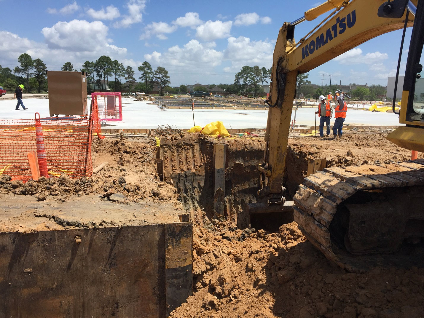
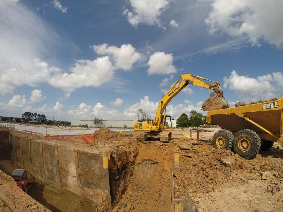
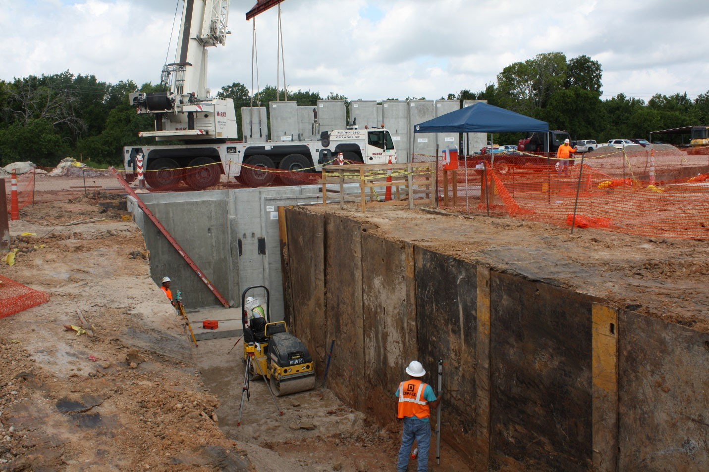
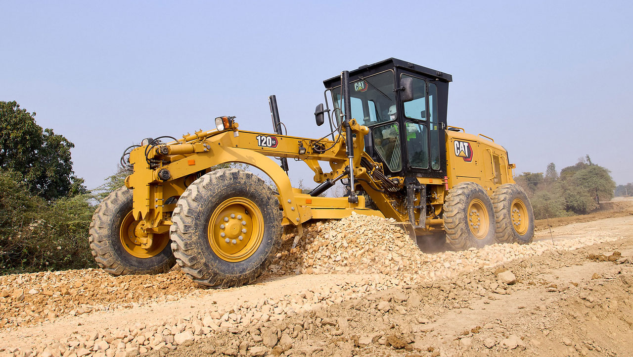
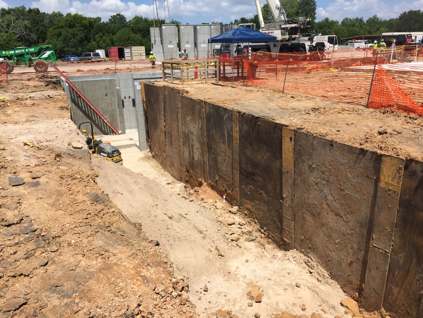
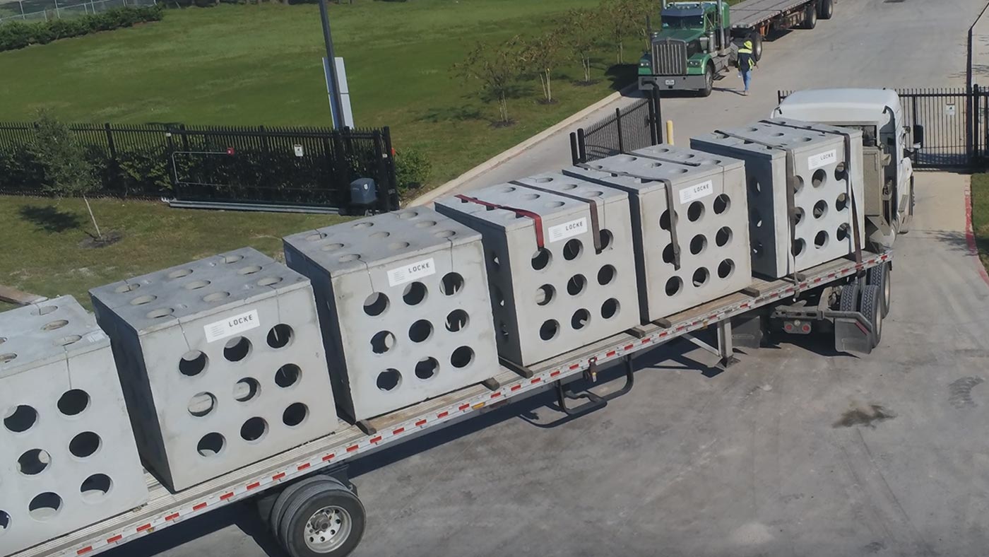
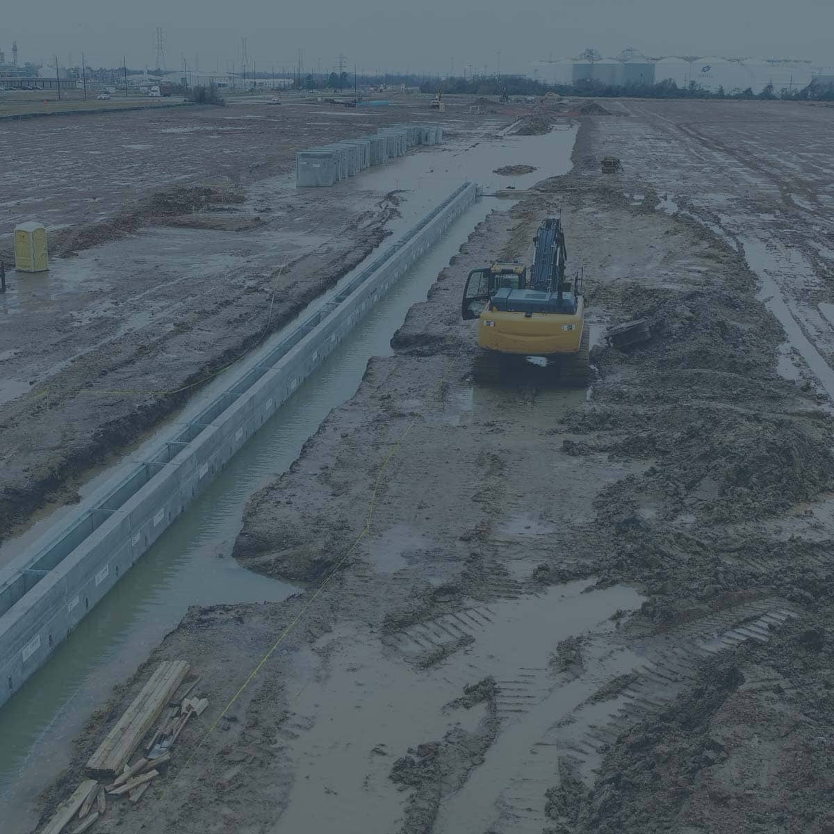
This image shows the potential heavy-duty traffic loading imposed on underground trench structures.


What does HS-20 traffic rating mean?

This is the term used by AASHTO and ACI to describe normal MOVING traffic loading conditions up to 18-wheeler loading. This loading assumes a 16,000 lbs wheel load and therefore a 32,000 lbs axle load. It also takes into consideration the additional loading that occurs from moving vehicles. These loads are called IMPACT and LIVE LOAD SURCHARGE and are an additional safety factors that help prevent underground enclosures from having a structural failure and collapsing in from traffic conditions. There are few construction materials that are designed to withstand these type of loadings other than concrete and cast iron (or ductile iron) steel. 

What is the difference between H-20 and HS-20?

Generally speaking, these terms are used interchangeably, but there is a slight difference. You can see the different diagrams showing the difference between H-20 and HS-20. There is minimal, if any, cost savings from designing structures with H-20 versus HS-20, so my recommendation is to always require HS-20 loading if you think there is any possibility of vehicle traffic.  

HS-20 vs H-20 Wheel Loads
This image helps show the difference between H-20 and HS-20 wheel loading and location.

What does the number “44” represent in HS-20-44?

Quite often, this number “44” is mistakenly assumed to mean 44,000 lbs in some design context. The number “44” actually refers to the year, 1944, in which the HS-20 traffic loading conditions were originally developed by AASHTO.

What is the difference between HS-20 and Tier 22 Ratings?

It is difficult to compare these two designations but there are some key points that people sometimes confuse when dealing with different load ratings.  One of the differences between these ratings, is HS-20 refers to traffic loading conditions with wheel loads up to 45,136 lbs, when considering impact and load factors, while Tier 22 is using a 33,750 lbs wheel load tested in a vertical position. The ANSI/SCTE 77 2007 code for the various Tier designations include Tier 5, 8 ,15, and 22 are meant for small boxes with only INCIDENTAL traffic conditions. Any underground enclosures with potential wheel loading conditions should consider using HS-20 traffic loading criteria and materials should be limited to concrete, steel, and/or cast/ductile iron materials.


Typical Container Yard Aerial Picture
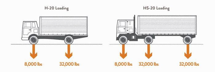
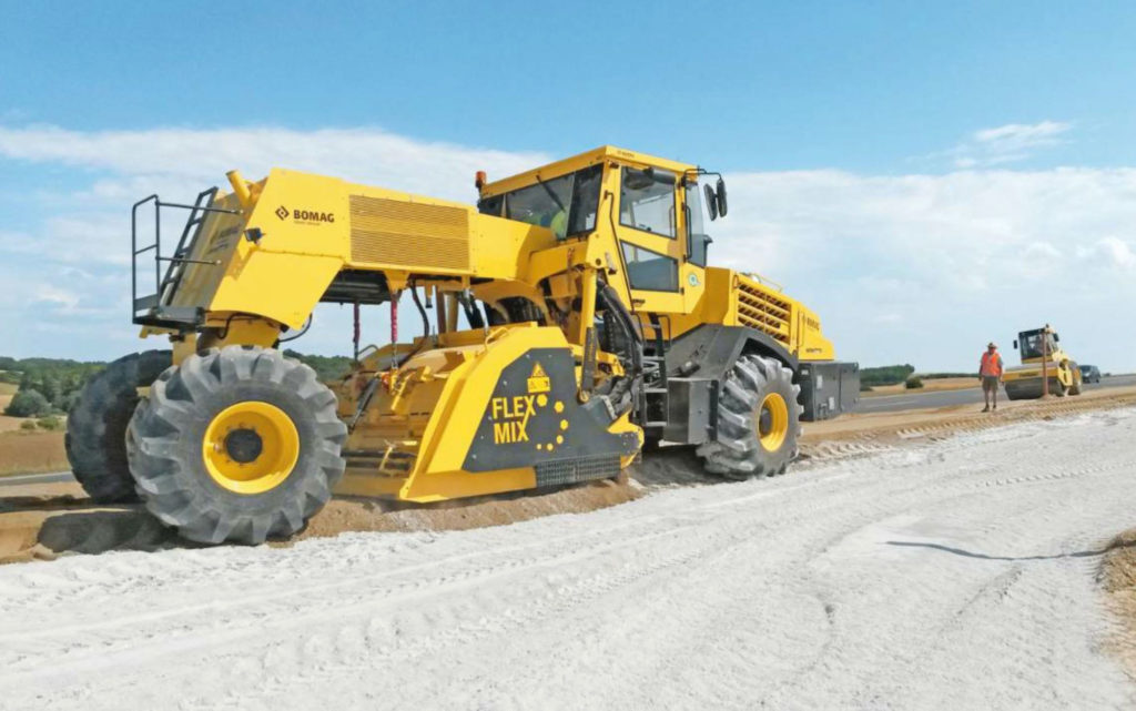
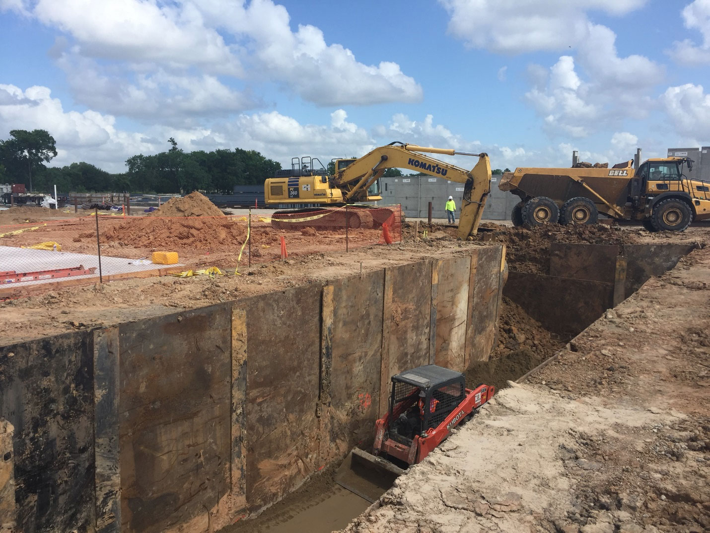
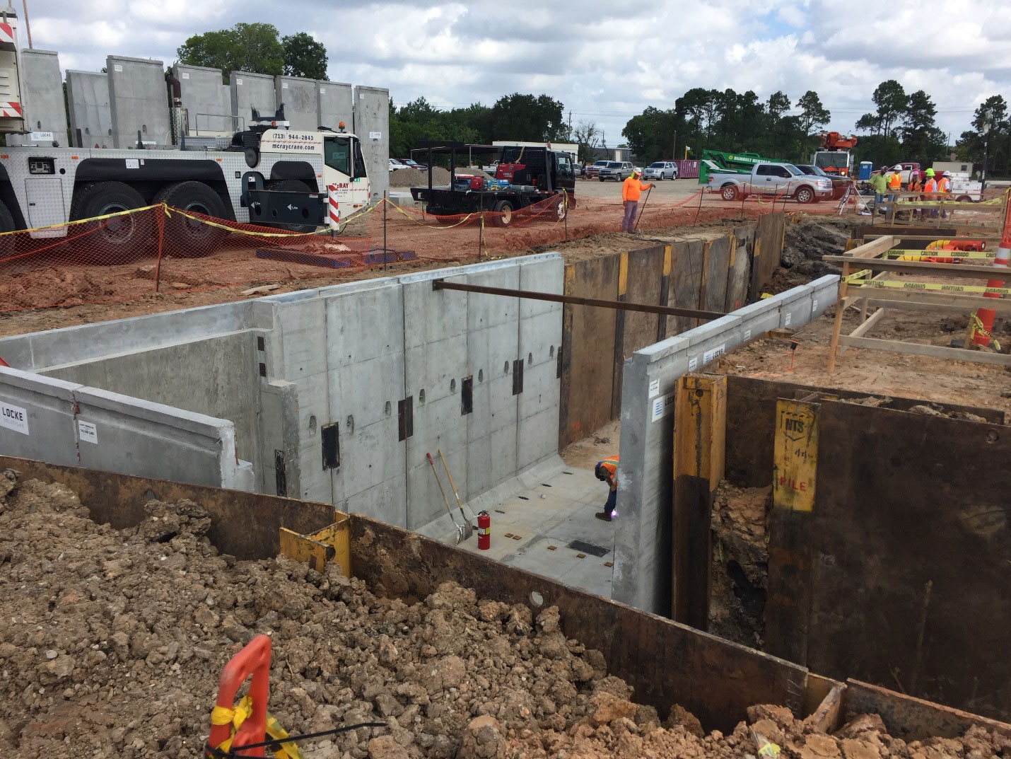
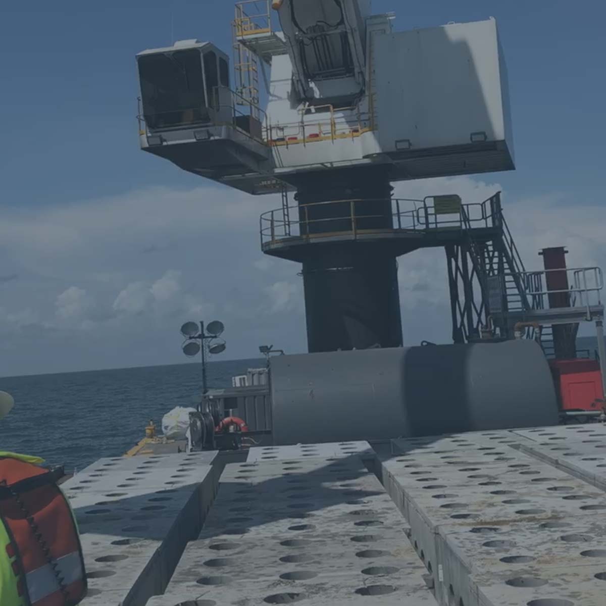
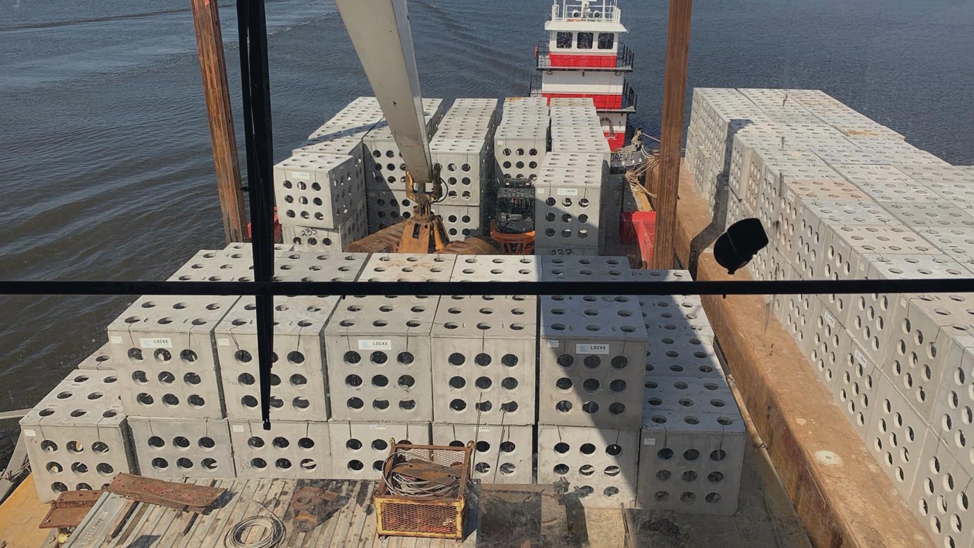
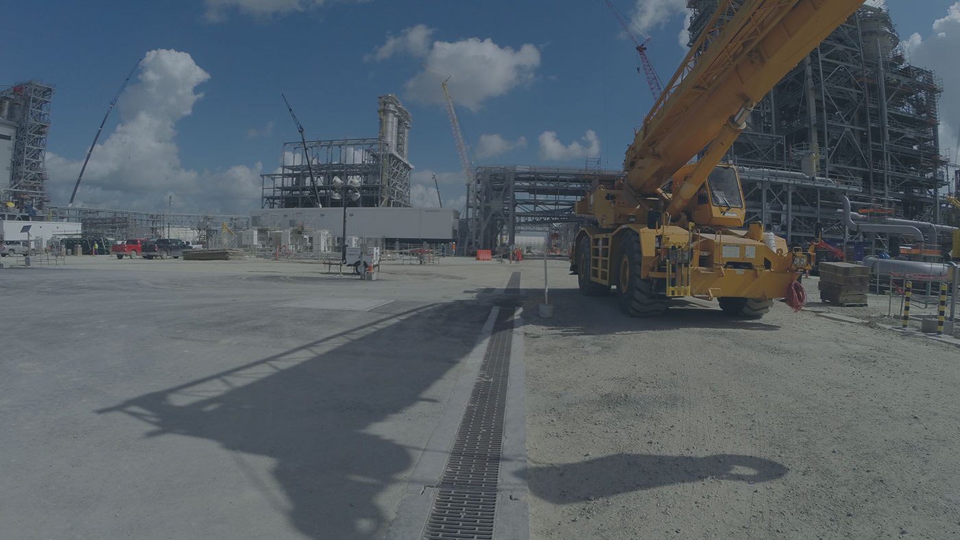
Many marine facilities have heavy-duty loading conditions due to storage containers and the equipment needed to handle these containers.


When do I need to consider designing above & beyond HS-20 traffic rating?

It is smart to consider special designs if you have larger than standard 18-wheeler traffic driving over your structures. Large construction equipment including front loaders, forklifts, mobile cranes all should be considered when installing underground structures. Airport, marine, and railroad facilities should also be looked at closely to determine what type of loading conditions will be present. From a cost/benefit analysis, it is very easy to justify the cost of a heavy duty load design versus the risks of a catastrophic failure because of an unexpected piece of equipment needing access on your structure.

What are the concerns when installing an underground enclosure?

The most critical factors include the type of loading conditions that could create a structural failure leading to the collapse of the enclosure. Vehicle loads on top of the enclosure dictate how the top and bottom of the enclosure should be designed. Lateral loads from soil, water, and loading derived from moving vehicles impact the design considerations of the side walls of an enclosure.

What is the difference between HS-20 and HL93?

HS-20 is the truck live loadings of the AASHTO specification, where H stands for highway, S stands for semi-trailer, 20 stands for 20-ton weight of the tractor (first two axles). Each axle will carry the loads as follow, the first axle carries 8,000 pounds, the second axle, 14 feet away carries 32,000 pounds and a single-axle semitrailer 14-30 ft away from the second axle carries 32,000 pounds.

HL93 is the Basic LRFD Design Live Load, where H stands for Highway, L stands for Loading and LRFD stands for Load and Resistance Factor Design. The HL93 design loading consists of a combination of “Design Truck Plus Design Lane Load” or “Design Tandem Plus Design Lane Load” which ever produces the worst case. A “Design Truck “is same as the HS-20 load. The “Design Tandem “consists of two axles, each axle weighing 25 kips spaced 4 ft apart. The Design Lane Load is equal to 640 pounds per linear foot. This uniformly distributed load is designed to apply on the above grade bridge deck but It does not apply to below ground structures per ASTM C1577. 

View more interesting precast concrete products here.