Leading Precast
Contact Sales
Tolerances are an important component of designing and manufacturing precast structures. There are different types of tolerances for precast, but the three main classifications of tolerances are interfacing tolerances, erection tolerances and product tolerances. Let’s talk about their differences and the common industry tolerance standards.
What is Tolerance?
First off, what do we mean by tolerances? Tolerance is the allotted variation that a structure can be produced based on the specified dimensions of the structure. For example, the industry standard tolerance height for an architectural wall panel up to 10 feet may have a ± 1/8 of an inch tolerance. The ± means that the allowed tolerance for the height of the wall can be 1/8 of an inch over 10 feet or an 1/8 of an inch under 10ft.
Product Tolerance
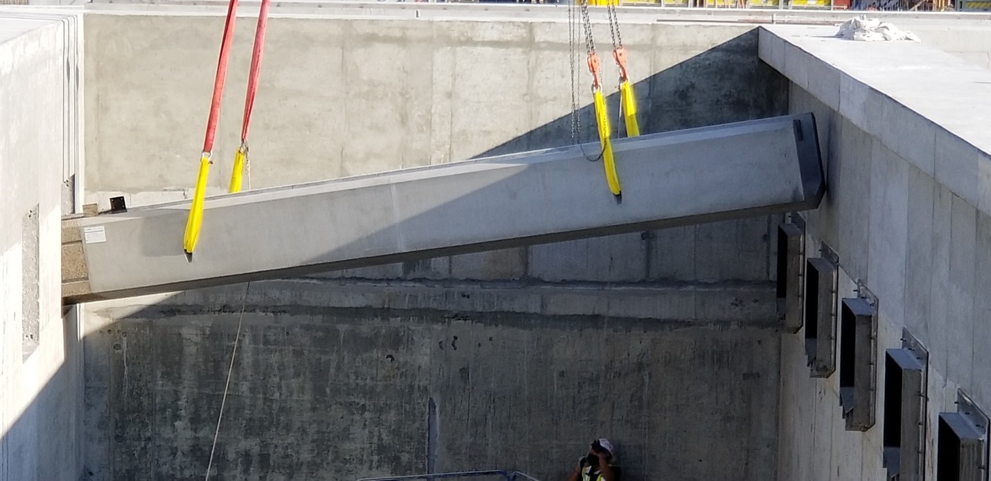
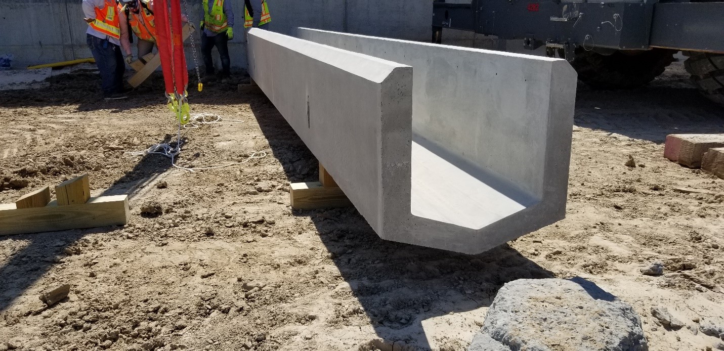
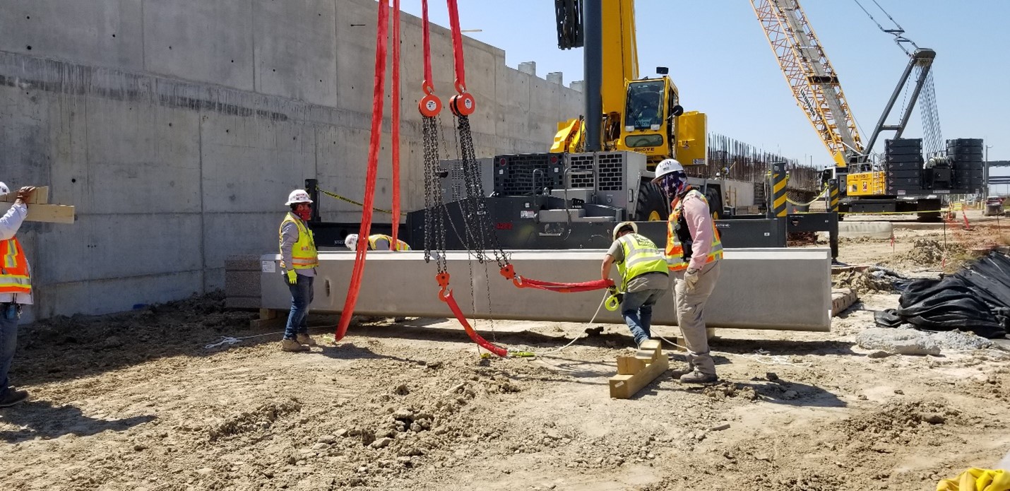
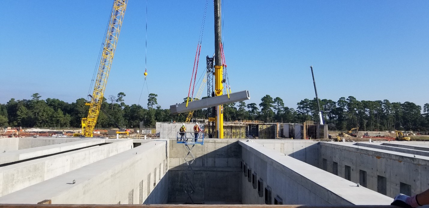
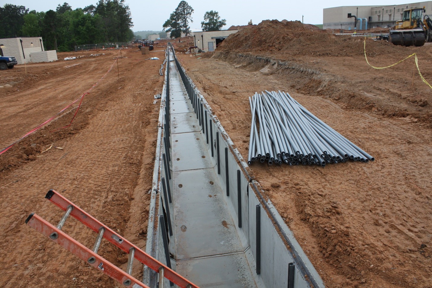
Let’s first discuss product tolerances. These tolerances are for the dimensional relationships of each precast component that make up the whole structure. Product tolerances are necessary ensure that all parts of the structure fit with one another. It is crucial that the form’s dimensions are correct so that the manufactured product has the correct tolerances. It is also important to have a clear understanding of the appropriate product tolerances before the project beings, along with the correct interfacing tolerances and erection tolerances. This creates clear expectations for the project, and it ensures that everyone is working within the same agreed tolerances. Flexibility of the form is important so that precise adjustments needed for the structure’s tolerances can be made and eliminate the chance for rework on the structure. Quality Control plays an important role with ensuring that the product is being produced correctly and if any of the forms are becoming warped or bowed past the allowed tolerance, adjustments will need to be made to correct this. There are also times when projects require extremely tight tolerances, such as this trough pictured above that required tolerances of ± 1/16. These types of tolerances can be challenging, as this only allows for an extremely small deviation from the specified dimensions.
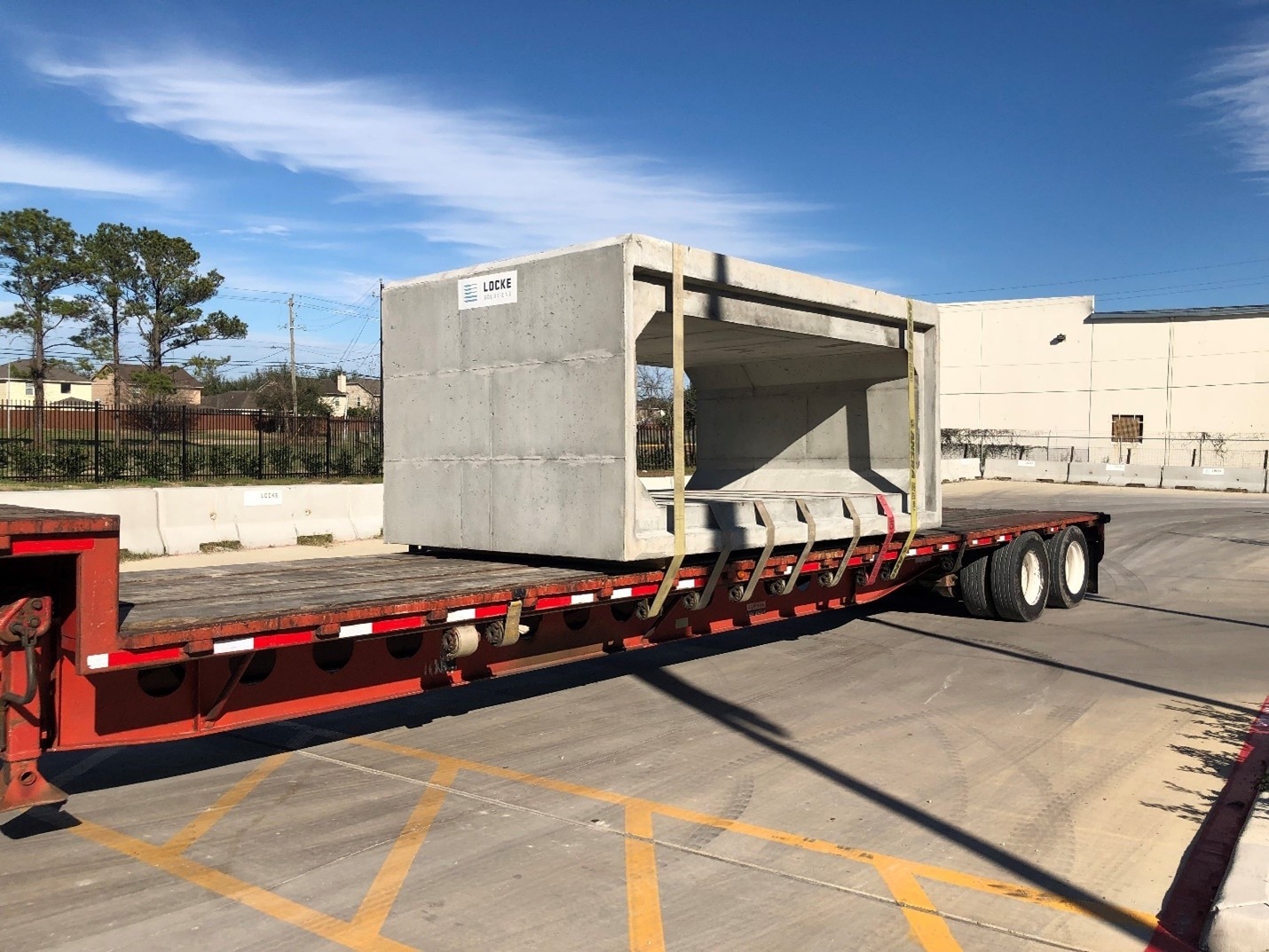
For example, Box Culvert industry tolerances require:
- Internal dimensions to remain within 1% from the design dimensions and haunch dimensions are not allowed to vary more than ¼ of an inch
- Variations of laying two opposite surfaces of the box section must not be more than 1/8 in/ft of internal span and may only have a maximum of 5/8 in. for sizing of internal spans through 7ft
- A maximum of ¾ inch for internal spans that exceed 7 ft with the exception where beveled ends for laying of curves are specified by the purchaser.
- Slab and Wall Thickness are not allowed to be less than 5% or 3/16 inch
- The length of the section that is underrun is not allowed to be more than 1/8 in./ft of length with no more than ½ in any area of the box section
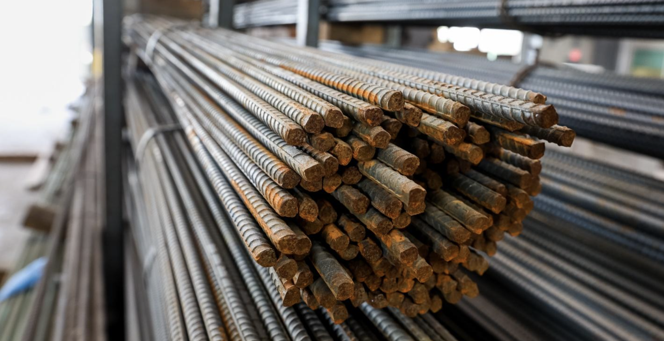
- The maximum variation for the position of the reinforcement of 5 inches or less for slab wall and thickness should be ± 3/8 inch or ± ½ inch for greater than 5 inches
- The cover that is over the reinforcement should never be over 5/8 inch
- Horizontal and vertical dimensions should be equal to the wall thickness and the steal area should increase a minimum of 1% for every 5% increase
- Areas for steel reinforcement should always meet the design standards

Image sourced from the National Precast Concrete Association
For precast concrete pipe, allowed tolerances include:
- An internal diameter of 12 inches through 24 inches and
- Pipes are not allowed to vary by more than 2% of the design diameter for a 12-inch pipe and no more than 1.5% for a 24-inch pipe
- Wall thickness should not vary more than ± 5% or 3/16
- The underrun portion of the pipe should not exceed more than 1/8in.ft and should not exceed more than ½ an inch for any pipe length
- Variations of laying the two opposite ends of the pipe should not be more than a ¼ of an inch. This applies to all sizes through a 24-inch internal diameter
- No more than an 1/8 of an in./ft for any size with a maximum tolerance of 5/8 inch for any length of pipe through 84 inches
- ¾ of an inch is the max for a structure with a 90-inch internal diameter unless when the structure has a beveled end pipe designed to lay on curves
- The maximum allowed variation for the circumferential reinforcement is ± 10% of the wall thickness or ±1/2 an inch
- The area of reinforcements will be considered acceptable so long as the nominal area of the wire or bars exceeds or equals the required specifications
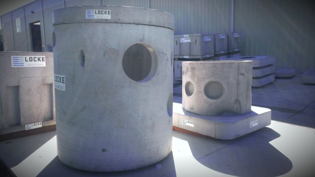
Industry tolerances for underground precast concrete utility structures:
For the dimensional tolerances measured on the inner surfaces including width, height, and length:
- 0 to 5ft has a tolerance of ± ¼ inch
- 5 to 10ft has a tolerance of ± 3/8 inch
- 10 to 20 ft has a tolerance of ± ½ inch
- 20 ft and up with have a tolerance that is understood and agreed between the customer and supplier
Squareness Tolerance
- 0 to 10 ft has a tolerance of ± ¼ inch
- 10 to 20 ft has a tolerance of ¾ inch
- And over 20 ft with have a tolerance that is understood and agreed between the customer and supplier
Joint Surface tolerances or the distance between joints without joint sealant
- Has a tolerance of 3/8 inch
Insert location
- Each component should not deviate more than ± 1/8 inch from specifications
Reinforcement location
- In accordance with wall thickness, the reinforcement should be within ± ¼ inch of the specifications and the cover should not be less than ¾ of an inch
- Spacing for the reinforcements should not be greater than 1 ½ inch or deviate more than 1/10 of the specifications for the bar spacing
Slab and Wall thickness
- The thickness of the wall and slab should not be less than the specifications, nor should it be greater than 5% or 3/16 of an inch
Warping and Bowing
Another type of tolerance that is important to mention is warping and bowing tolerances. These tolerances are especially important when aligning precast wall panels. These tolerances influence the way that the edge of the panels align with one another during erection. Bowing is when the two opposite ends of the panel fall on the same surface, and the section of the panel between the two edges become out of plane. It is more common that thinner panels will bow before thick panels bow. Due to this, tolerances for thinner panels are generally more lenient.
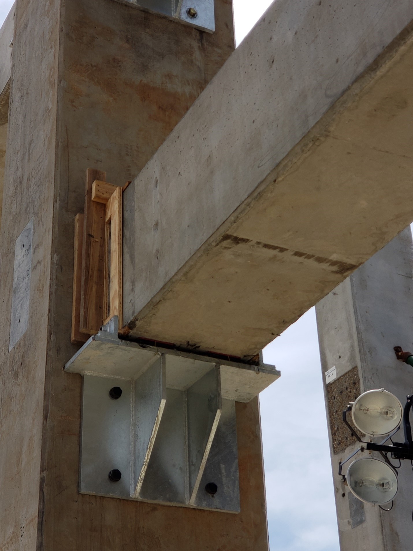
Corbel Location
Certain structures also require corbels or haunches, which are components that are anchored on a wall to support the weight of a structure. These components also have tolerances. Typical haunch-to-haunch tolerance is ± 1/8 inch to ± ¼ inch.
Erection Tolerances
Erection tolerances are the tolerances for when the precast structures are set in place. While all tolerances are important when designing and building precast structures, erection tolerances are especially important because they give the allowable tolerances of how a precast structure should be set in its final place. This also influences the way that other components of the structure will set in place. Equipment also plays a significant role with erection tolerances. Due to this, variation of some of the tolerances may be necessary, especially for more custom products. If erection tolerances are too constraining, this can present challenges for the precaster and costs of installing can become more expensive due to the special equipment that may be needed. To help ensure that the structure is erected properly, all dimensions of the structure should be checked prior to starting erection. After this takes place, the structure or precast components should be checked to ensure that they are within tolerances. Here are a few examples of common industry standards for erection tolerances:
- A precast concrete component to another precast concrete component has a ½ inch (1 inch preferred) recommended clearance
- A precast concrete component to a steel component has a 1 inch (2 inch preferred) recommended clearance
- A precast concrete column cover has a 1 ½ inch (3 inch preferred for taller structures) recommended clearance
Interfacing Tolerances
Interfacing tolerances are the tolerances associated with other systems or materials that interface with other precast components. They are needed prior to or after the interfacing system is erected. For systems that have multiple precast components, it is important to understand the allowable variations in the dimensions associated with other materials or systems that are in contact with or that are near the precast concrete. Interface tolerances can involve structural steel, and even windows, doors, and ventilating systems and heating systems.
Final Thoughts

Tolerances play a key role in the design and function of precast structures. It is important to remember that the details of connections must be considered when specifying erection tolerances and adequate spacing must be provided to perform the tasks necessary to complete the connection. The engineer may also choose to specify a minimum bearing size for various precast concrete products. It is also important to remember that precast structures that do no meet tolerance specifications can be rejected. To prevent this from happening, the best plan is to ensure that you as the customer, the engineer and your precaster are all on the same page.
Stay tuned for our next article.
We hope this article was helpful. Please send in your questions to info@lockesolutions.com and we would be happy to help answer them.