Understanding the differences between precast concrete and cast-in-place concrete is often misunderstood. The primary difference is the method of construction, but the finished product should be nearly the same or identical. There are several key differences between these two types of construction methods. Recognizing and understanding their differences will help you to choose the method that will be best for your project’s specific needs. This article will be geared more towards the construction of underground concrete structures.
What does Cast-in-Place mean?
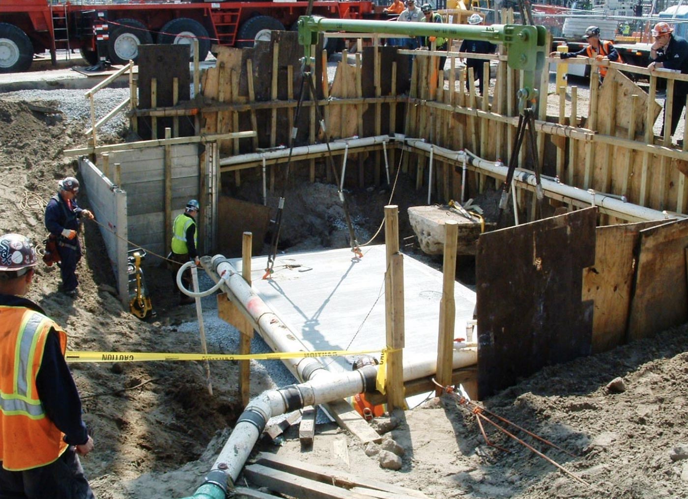
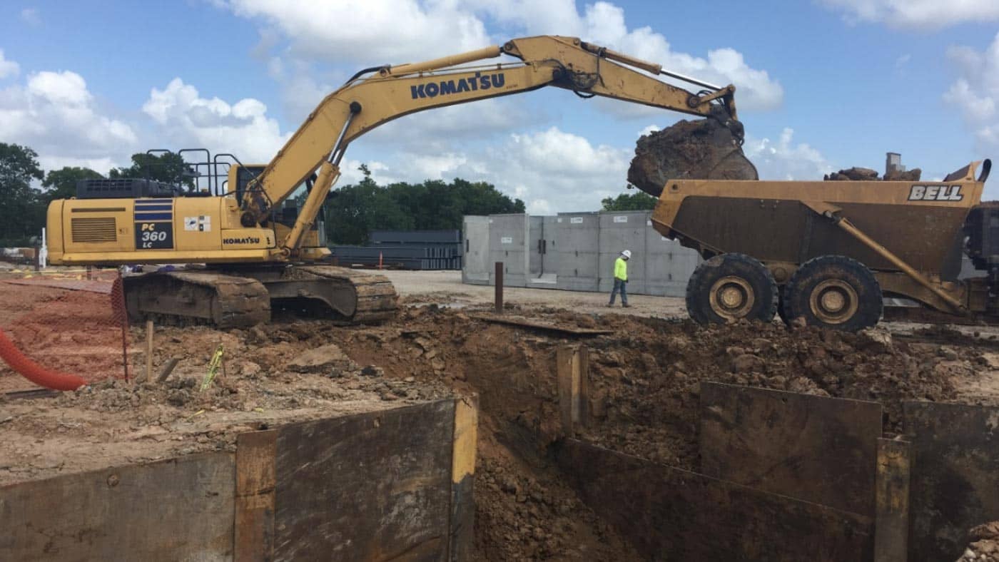
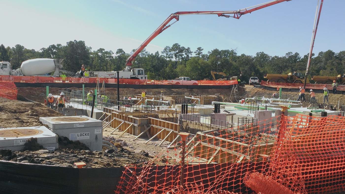
The term “Cast-in-Place” is used for the construction method of placing concrete and curing on-site and is also sometimes referred to as in-situ casting or pour-in-place. “It’s the most prevalent form of concrete construction, which consists of creating a mold onsite primarily using wood or steel panels and placing concrete directly to the final position of the structure” explains Asher Kazmann. The concrete is normally transported in a ready-mix concrete truck to the job site in an unhardened state. Once on-site, the truck will place the concrete directly in the final position if it is able to get close enough to access it, otherwise, the concrete is placed in a pour bucket or into a concrete pump truck. A pour bucket may be moved with a crane or excavator to its destination while a pump truck can pump the concrete through piping vertically or horizontally up to around 200 feet away. Common uses of the cast-in-place method include parking lots, road paving, and housing foundations.
What does Precast mean?
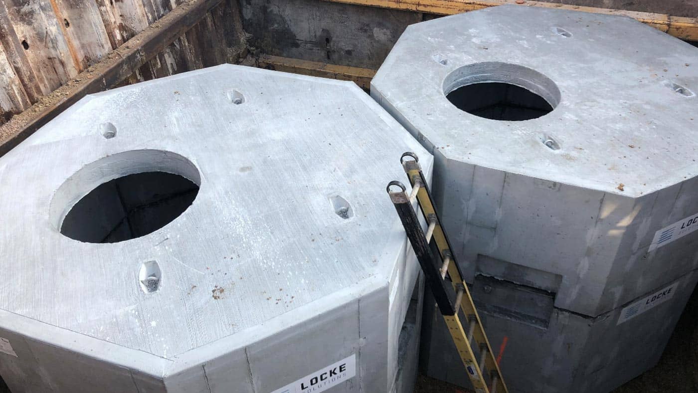
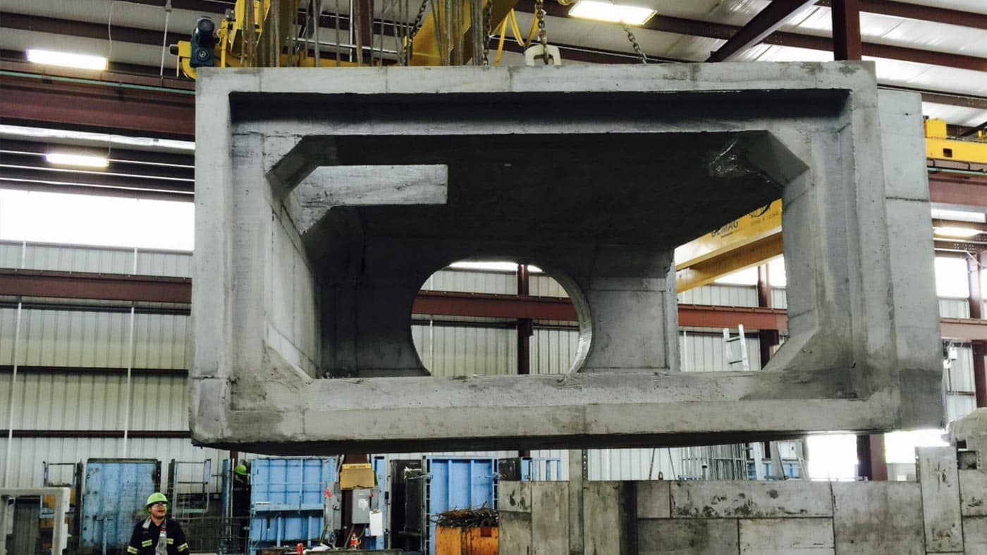
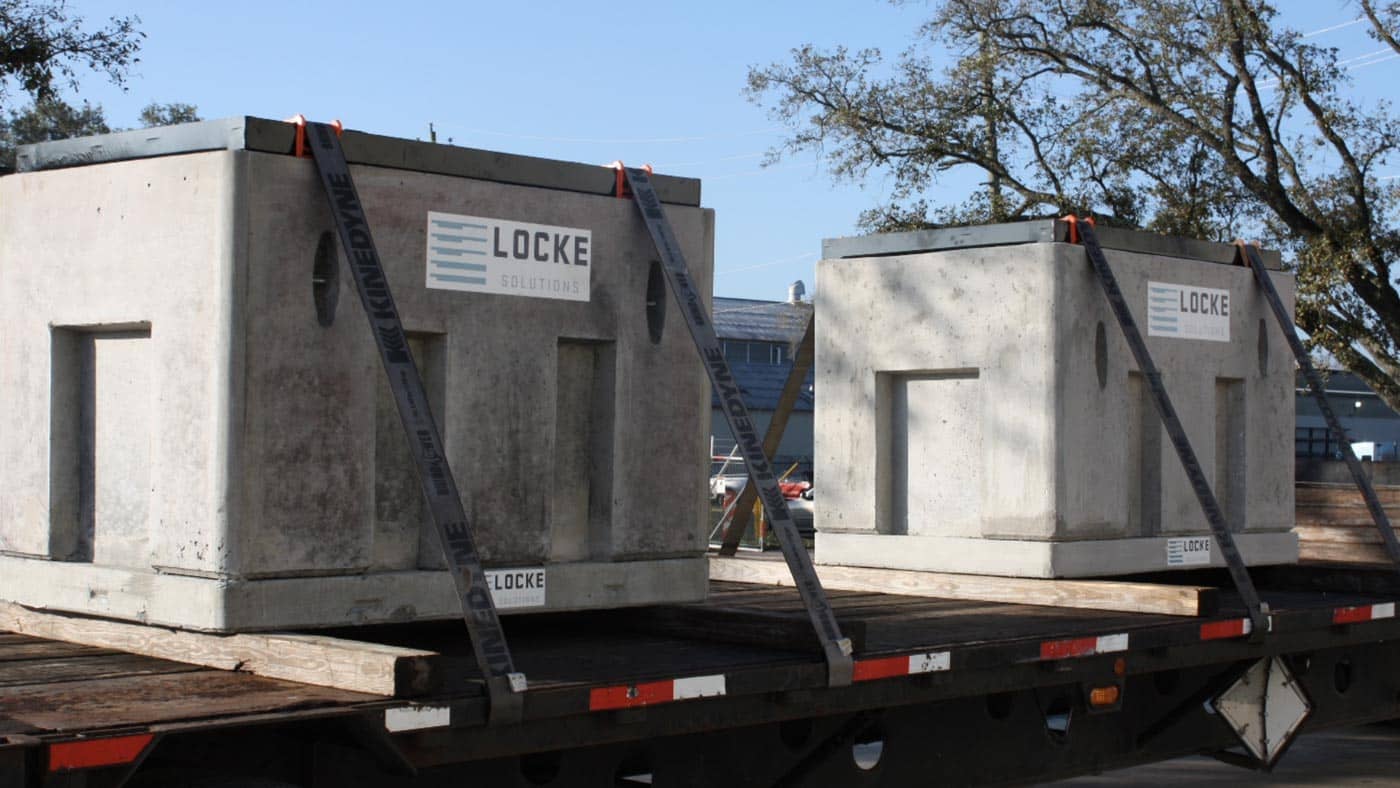
Precast concrete structures are prefabricated and cured off-site. Precast structures are fabricated in a similar fashion as cast-in-place structures, except they are fabricated prior to installation in a manufacturing plant. Common structures precast include wall panels, trenches, staircases, septic tanks, grease traps, bridge beams, box culvert, and pipe.
Installation Process for Cast-In-Place Construction Method
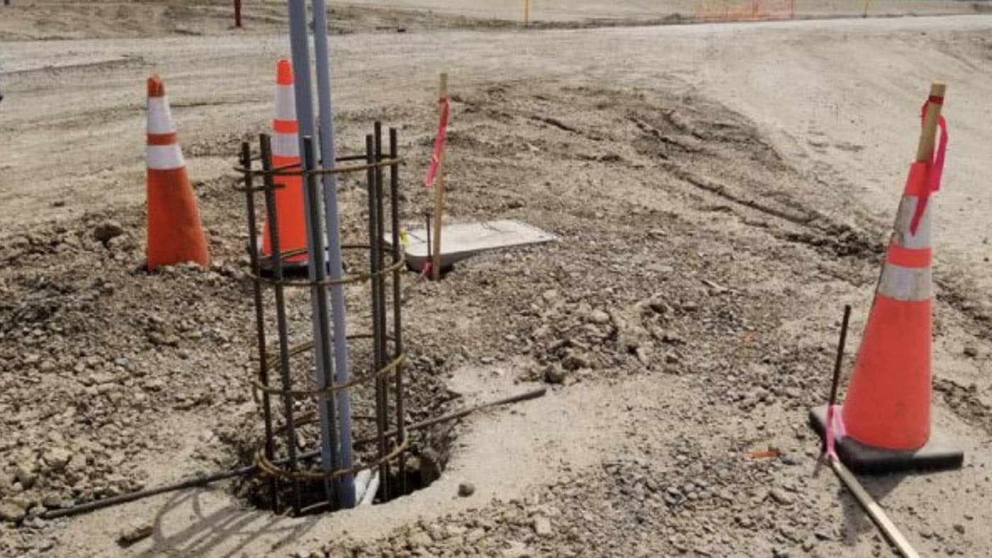
The process of concrete construction using the cast-in-place method is virtually the same for all underground concrete structures. Here are the basics steps.
- Excavating, shoring, and prepping the subgrade.
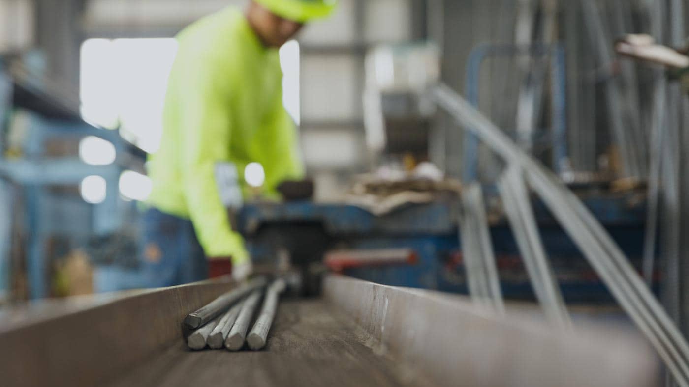
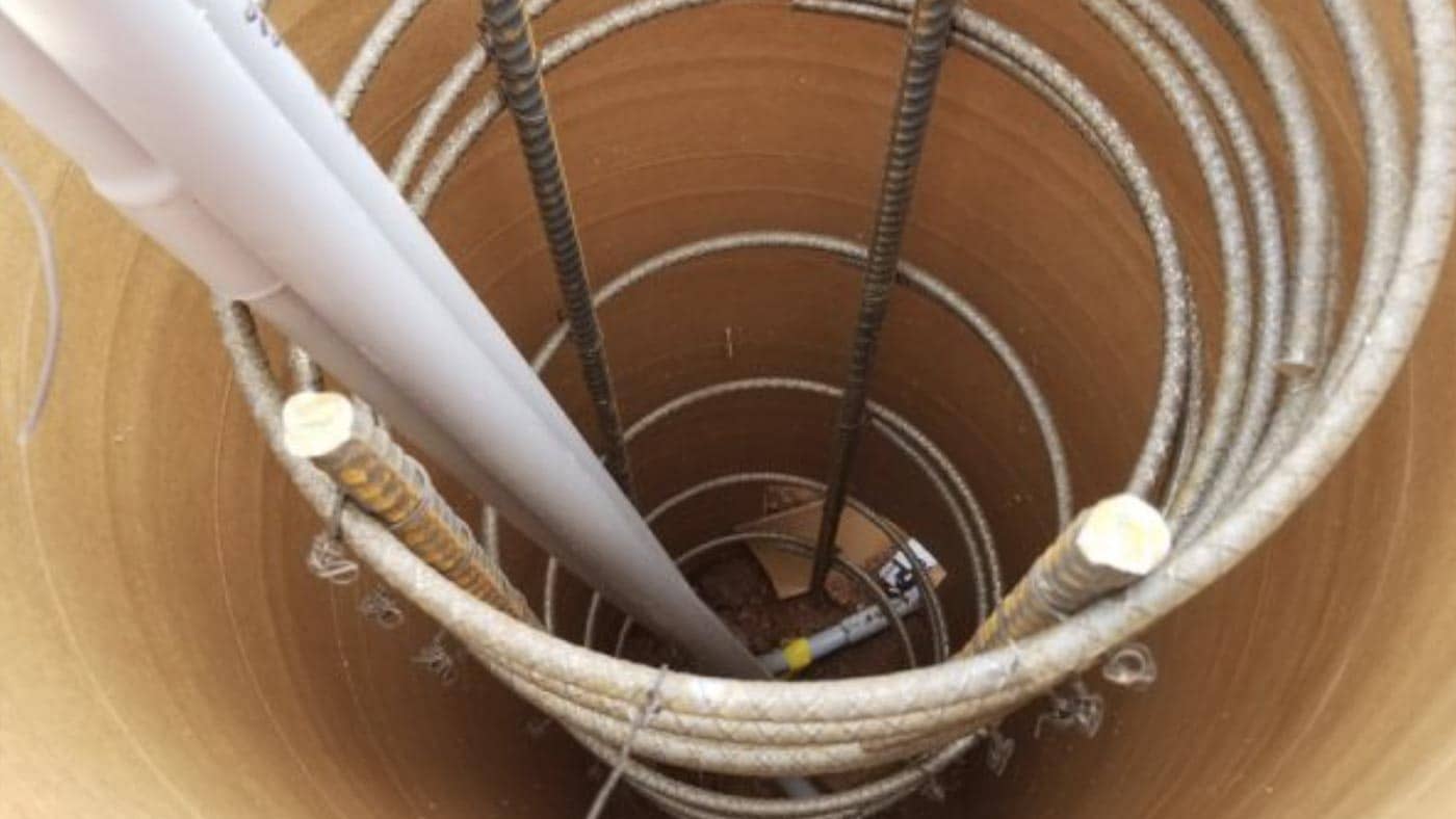
- Fabrication and tying of the steel reinforcing rebar. Often this step is performed by a separate trade referred to as rodbusters and generally, the rebar is prefabricated offsite, where it is cut and bent to specifications. The rodbusters will assemble and tie the rebar and place it in the proper position in the excavated area.
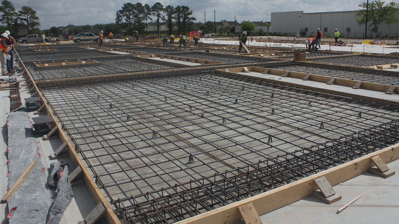
- Formwork is set in place around the structure. This is the wood or steel panels that are assembled to hold the fresh concrete in place long enough to harden. This formwork can be fabricated by carpenters or purchased by companies such as Dayton Superior Symons Panels or EFCO Forms.
- At this point, there is usually an inspection required by a third-party firm to verify the proper spacing and clearances of the reinforcing steel relative to the formwork and check that the overall dimensions of the formwork are within tolerance of specifications.
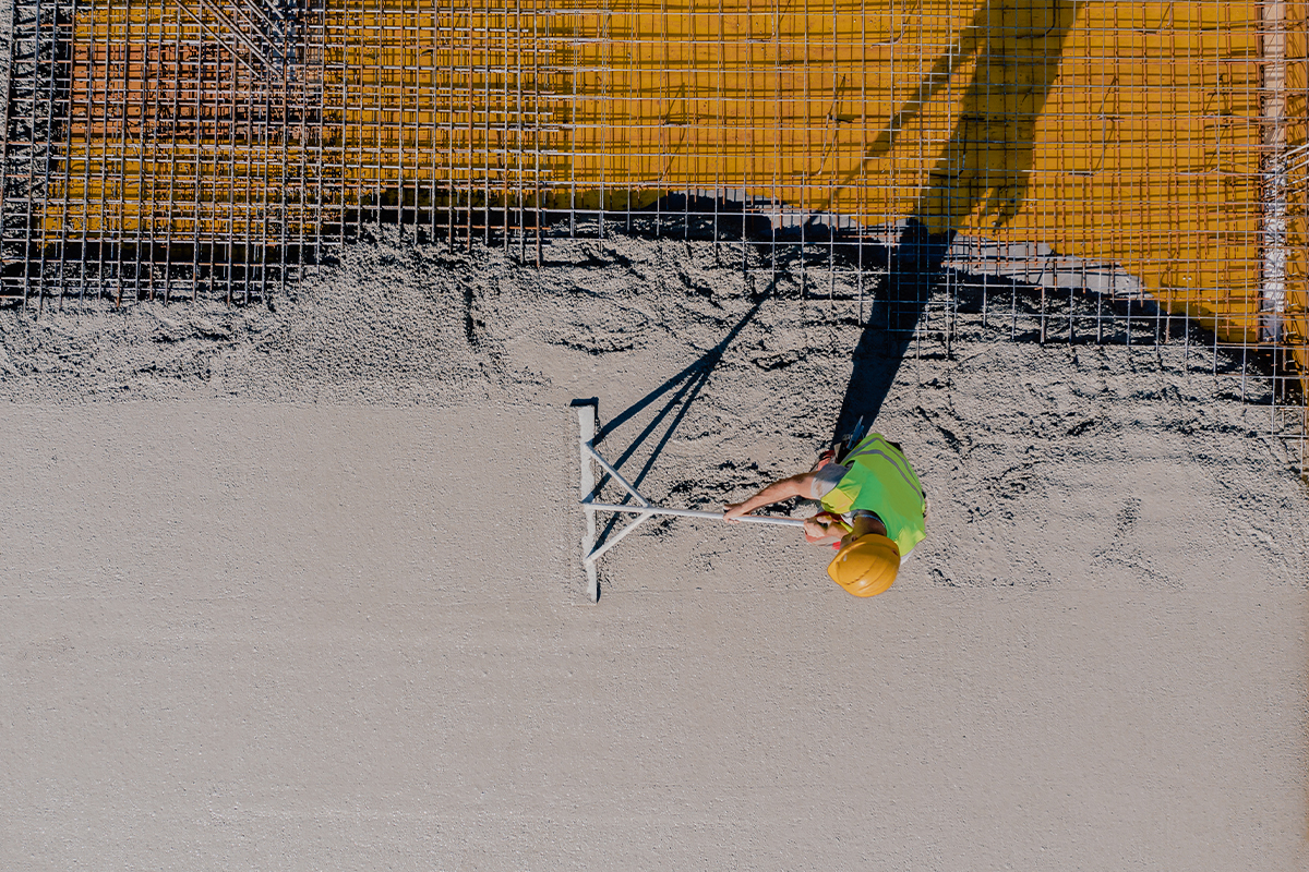
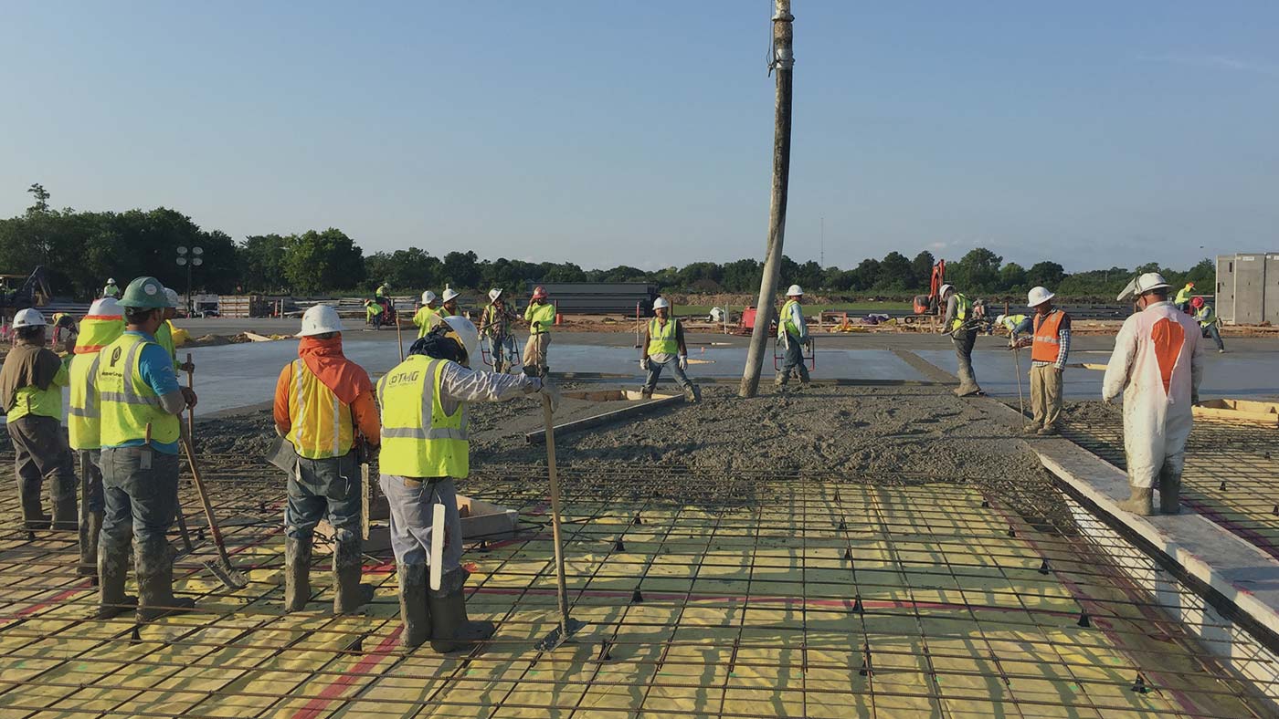
- Once inspections have been cleared, the concrete can be placed. It is important to confirm the formwork has been braced properly to withstand the hydrostatic pressure of the fresh concrete to prevent any movement of the forms or worse, a “blowout” of the formwork. Also, a third-party inspection firm will typically take concrete samples during the concrete placement for future verification of concrete strengths and specifications.
- After placement of the concrete, it will need anywhere from 3 to 28 days to cure, depending on the concrete curing specifications and strength requirements. The strength of the concrete is often confirmed by performing proof load compressive strength tests on sample concrete cylinders.
- Once curing requirements are met and the concrete has reached the required strength, the formwork can then be removed.
- Any required patching or clean-up can be performed at this point and a final inspection is done to confirm the dimensions of the concrete structure still meet tolerances.
- Finally, backfilling can take place. The backfilling process typically takes place in several layers of backfill anywhere from 6” to 18” at a time while compacting each layer during the process.
Installation Process for Precast Concrete Construction Method
The process of concrete construction using precast concrete structures is similar to cast-in-place with the exception that many of the steps are done offsite. Here are the basics steps.
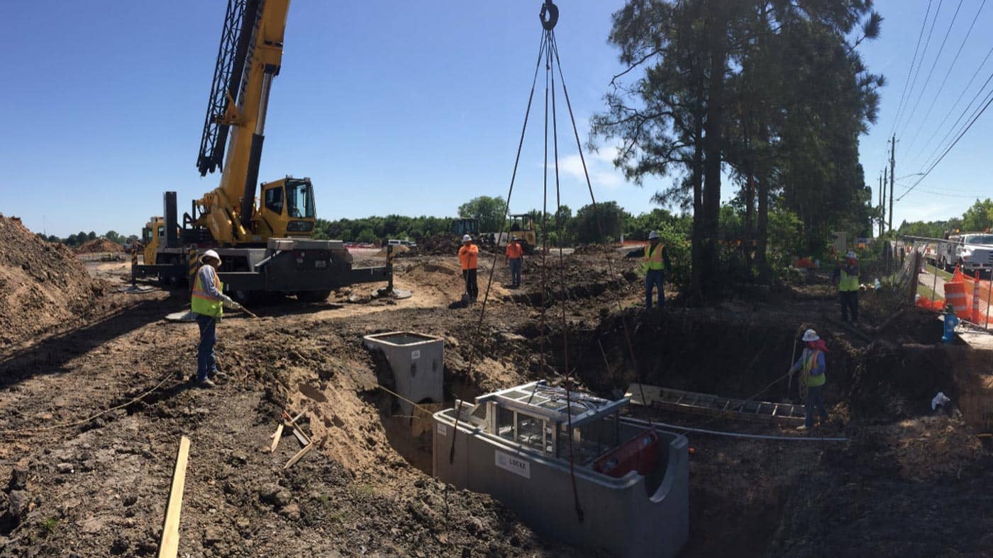
- Excavating, shoring, and prepping the subgrade.
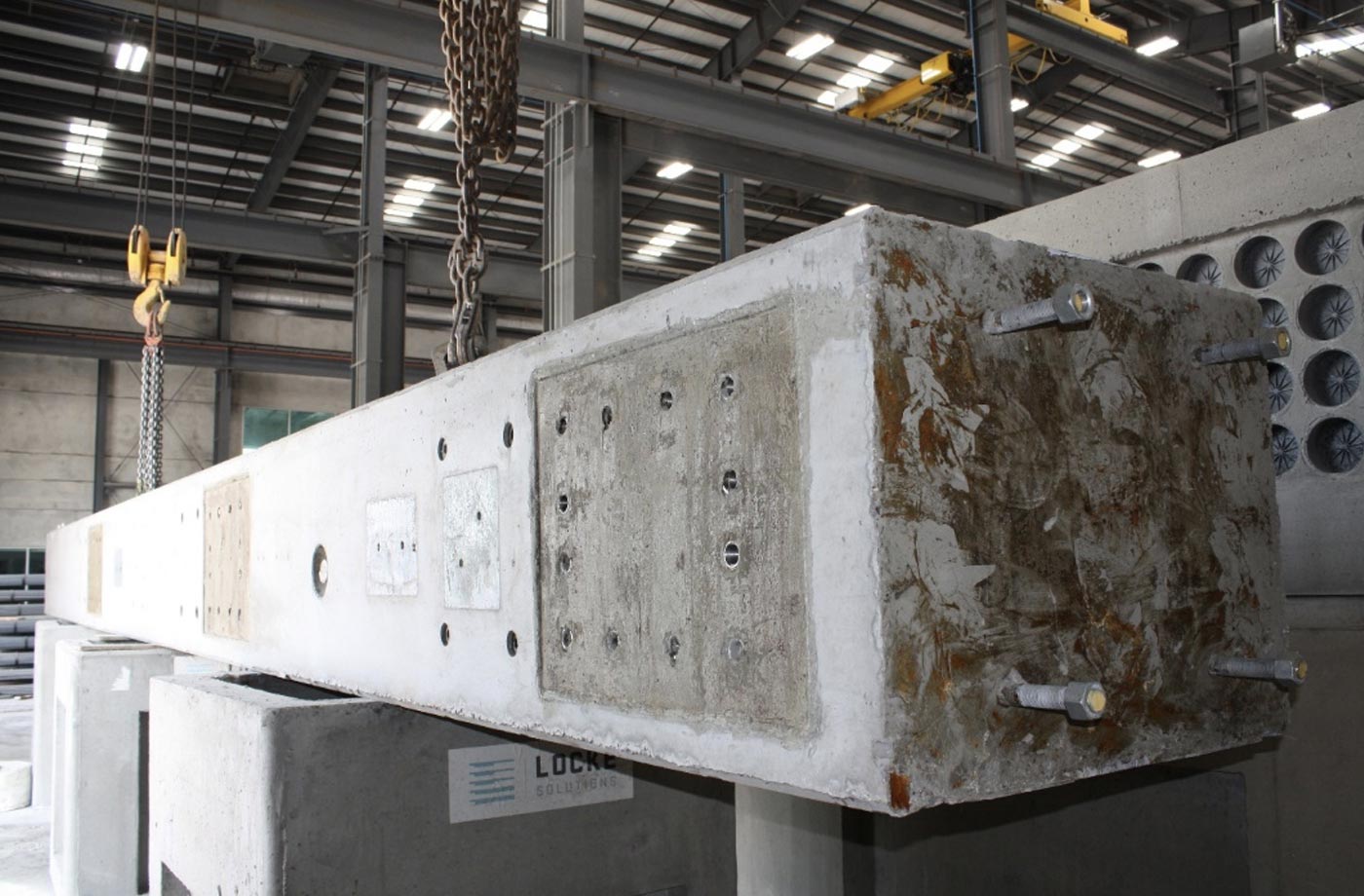
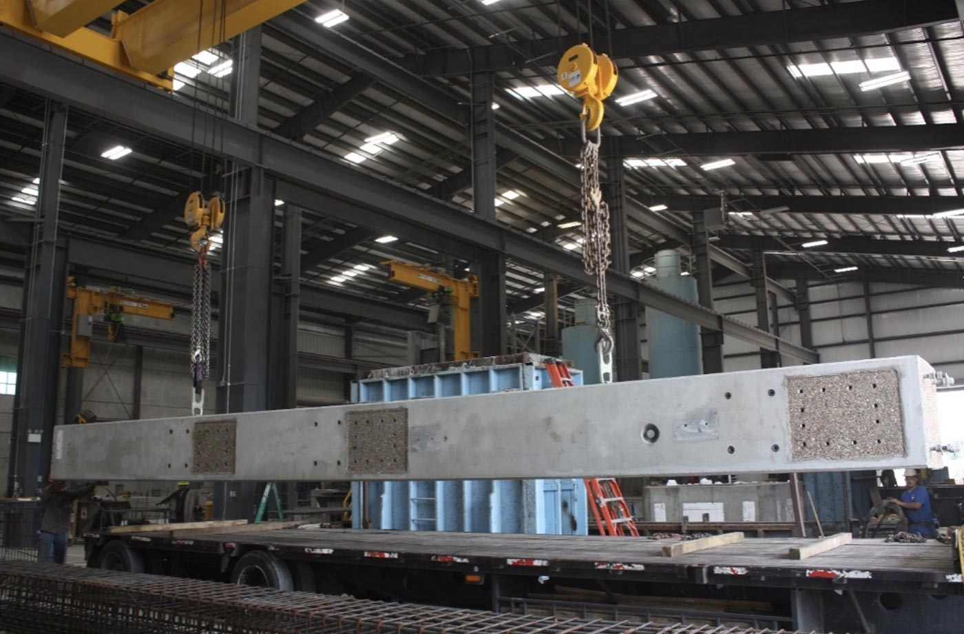
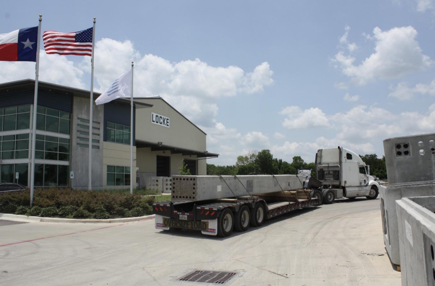
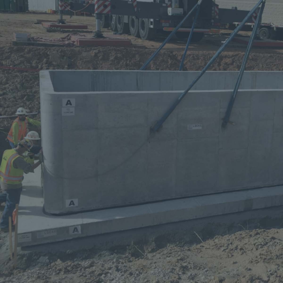
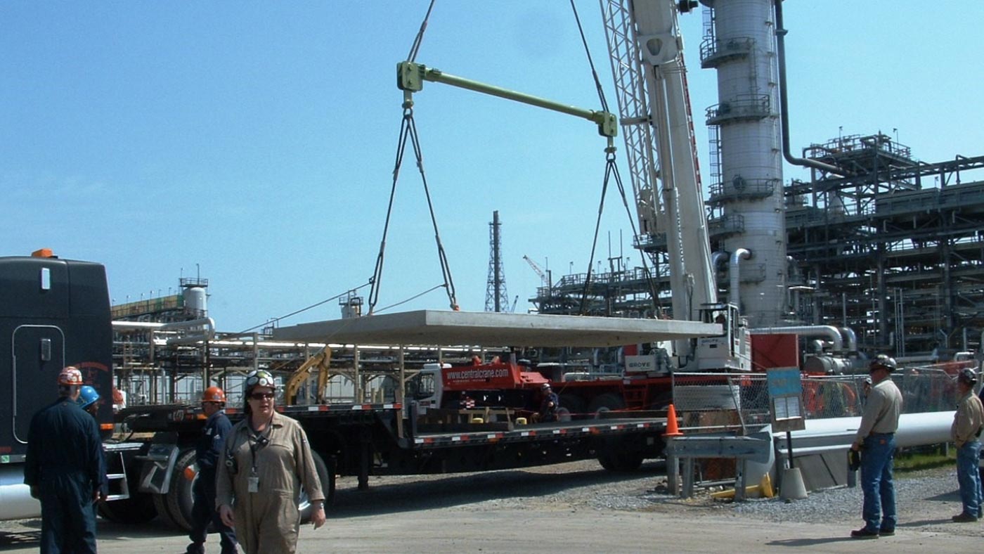
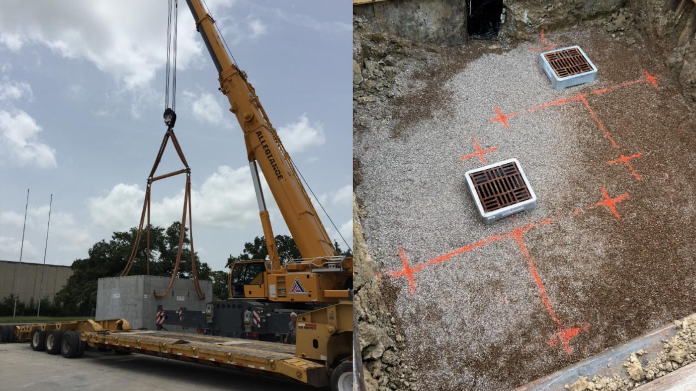
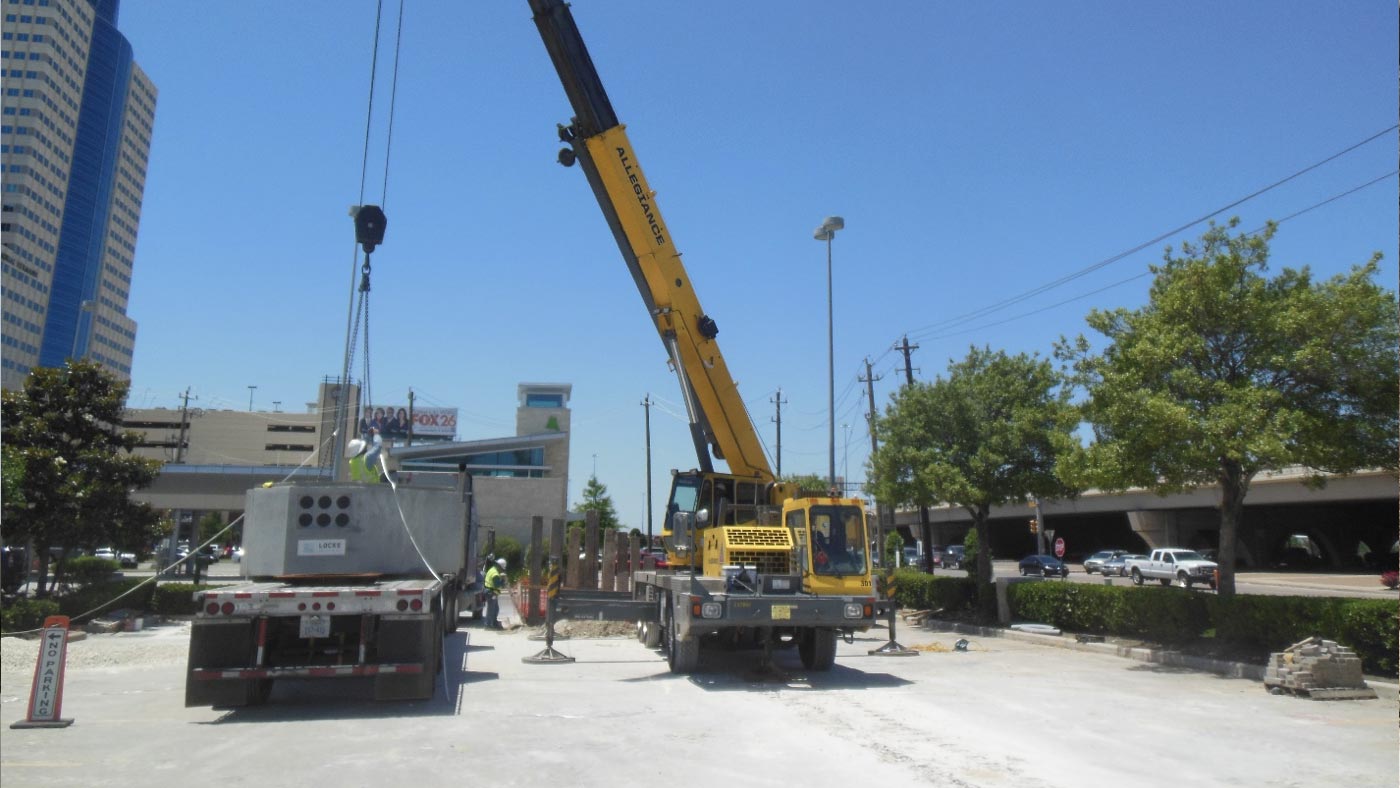
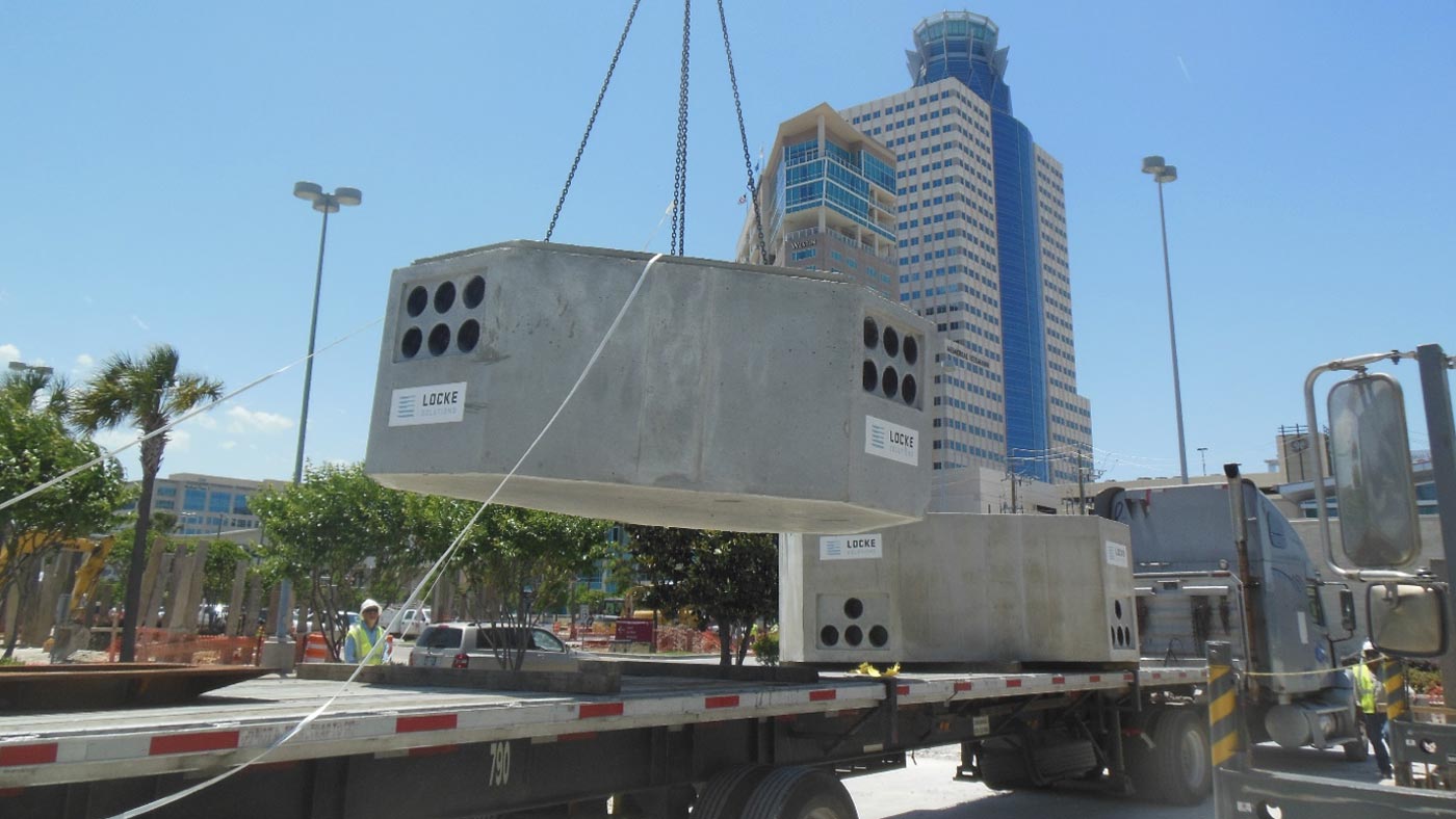
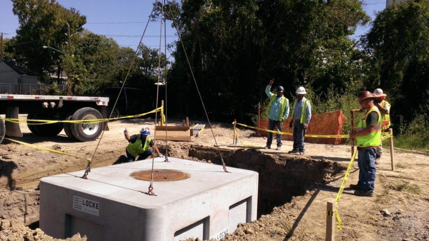
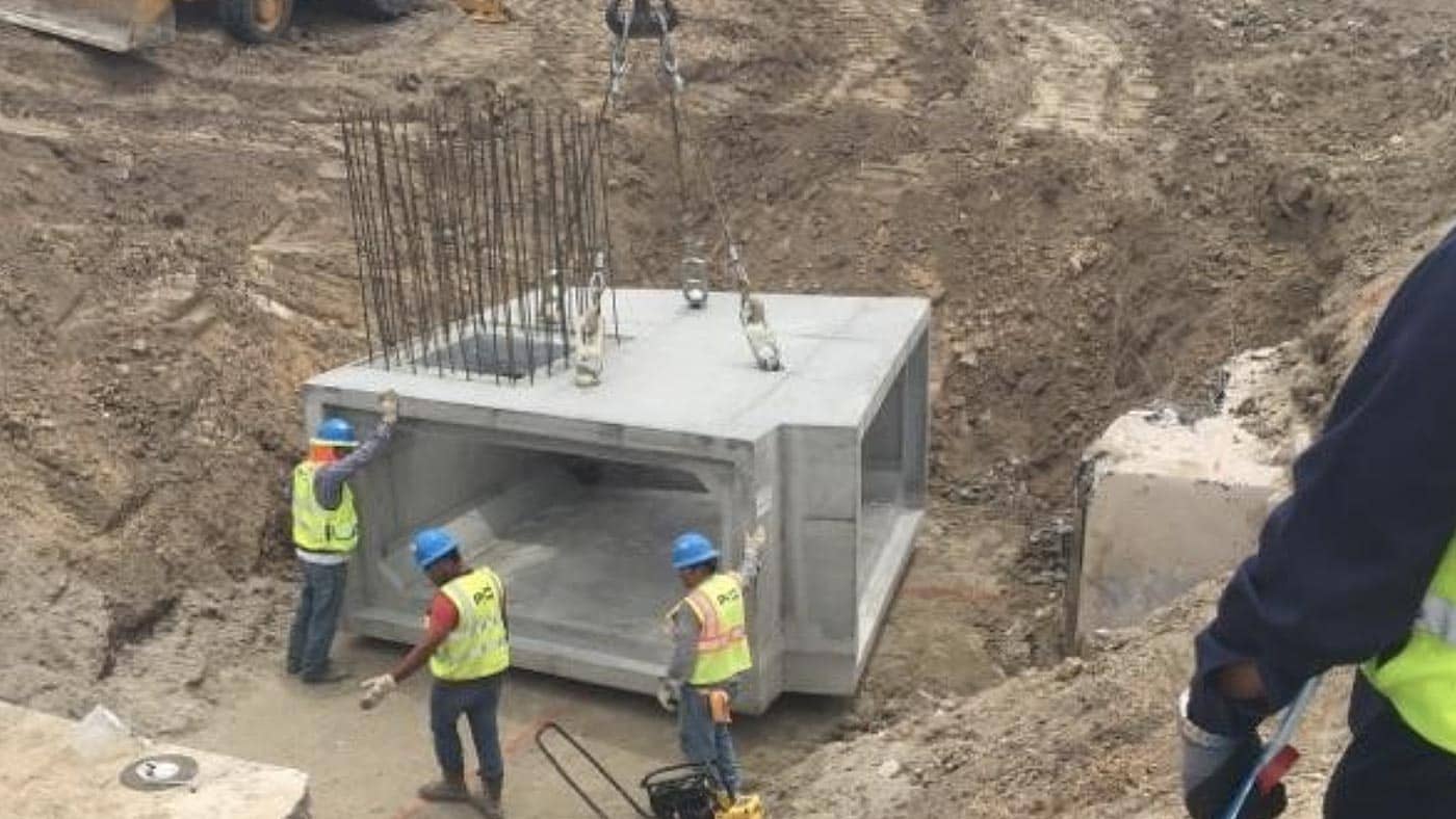
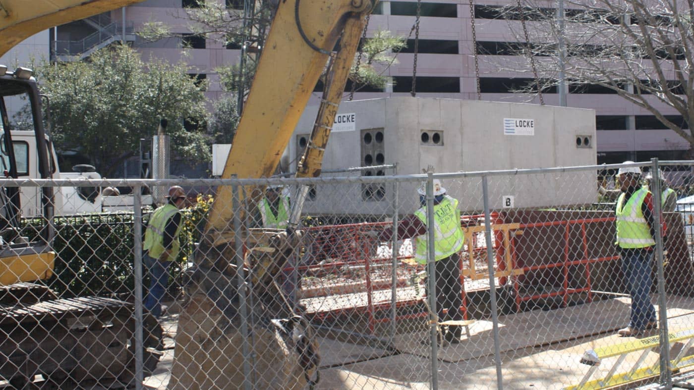
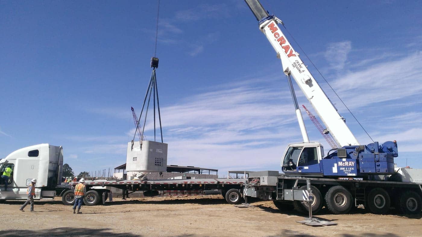
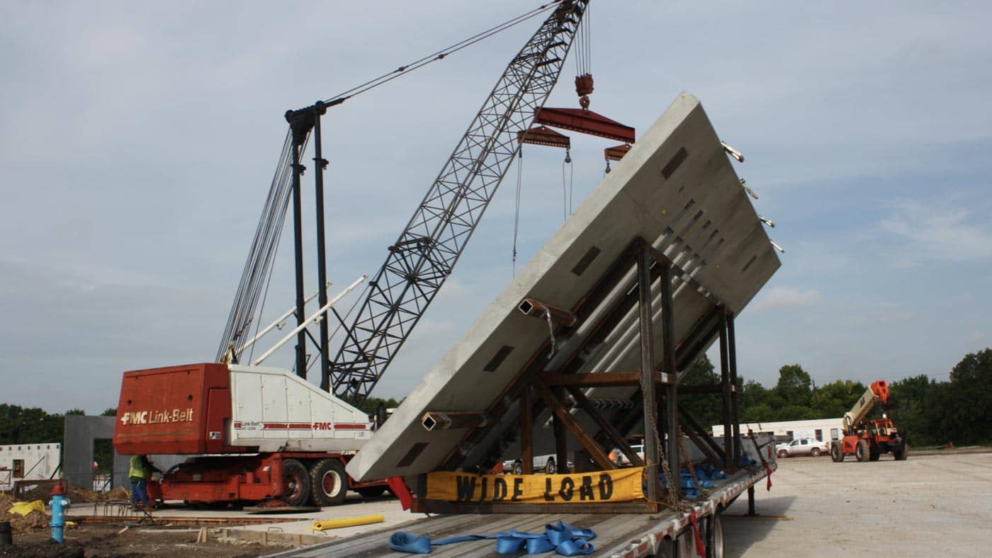
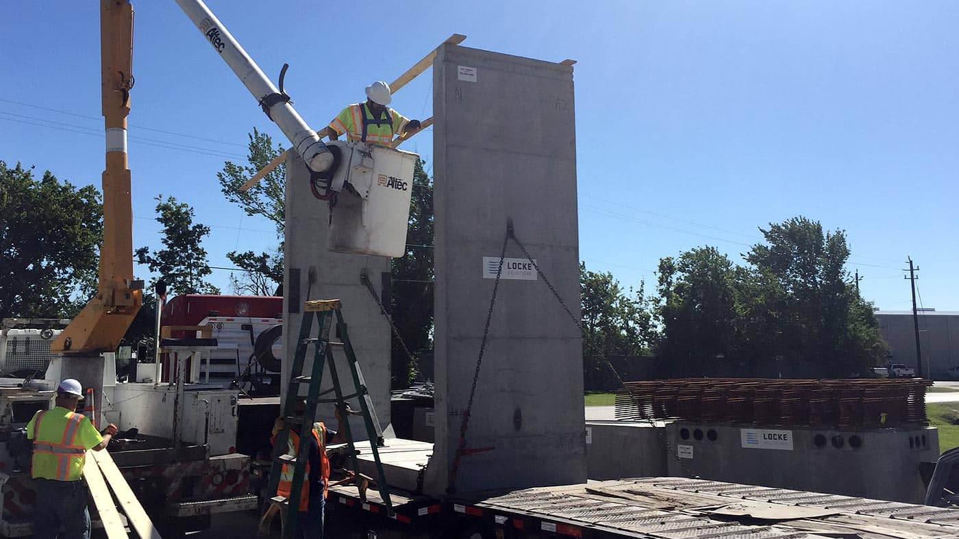
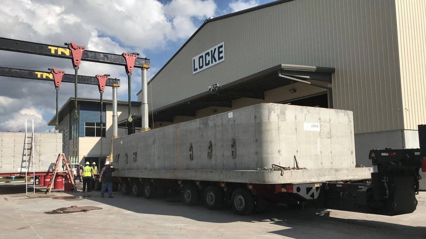
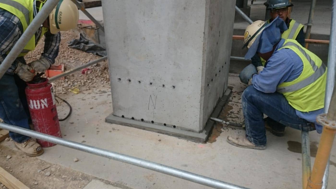
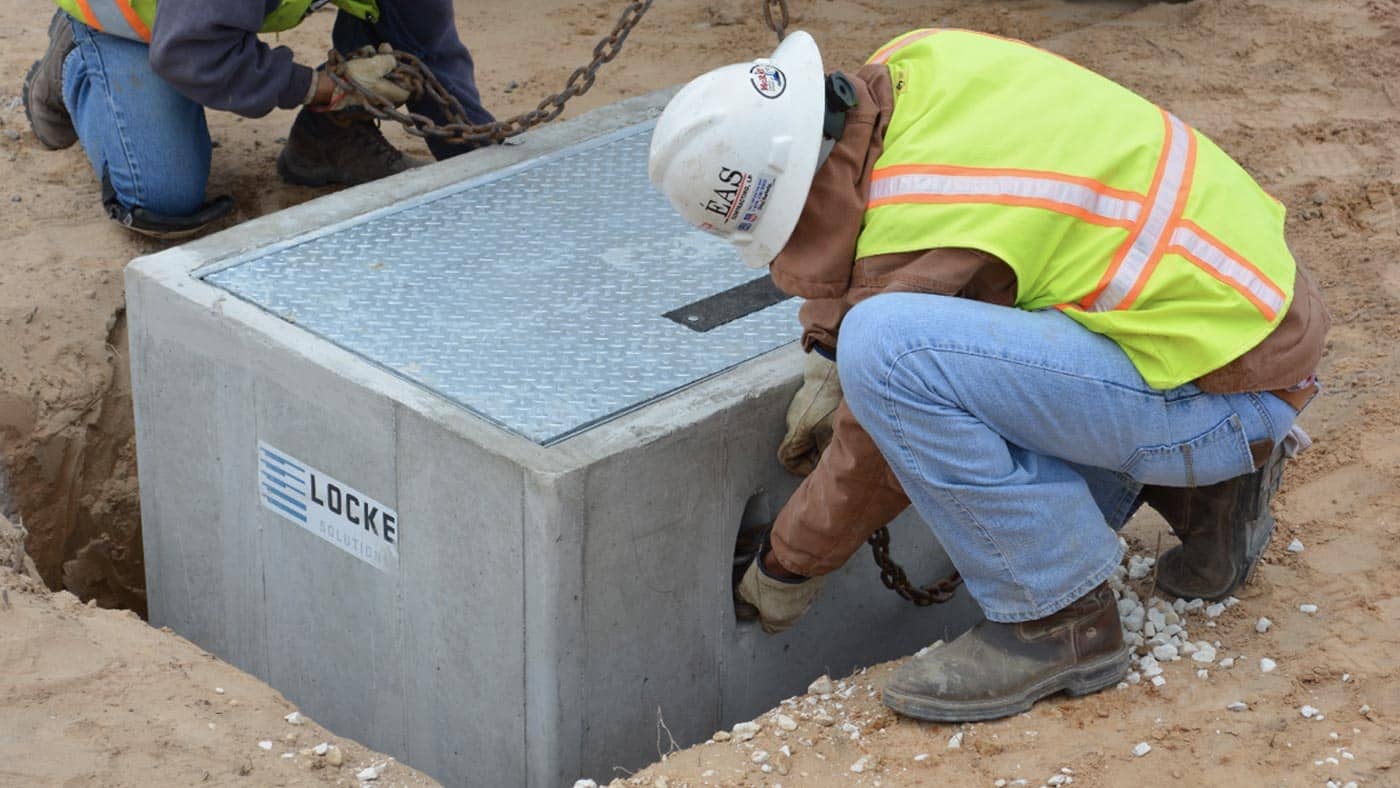
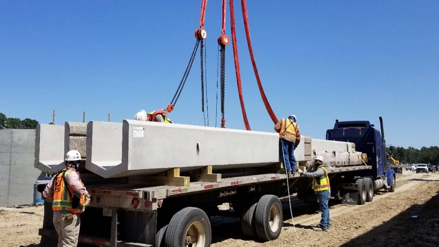
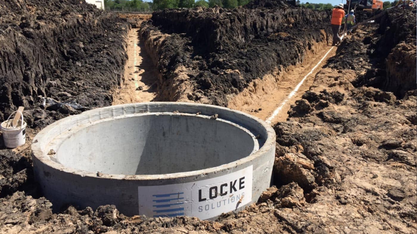
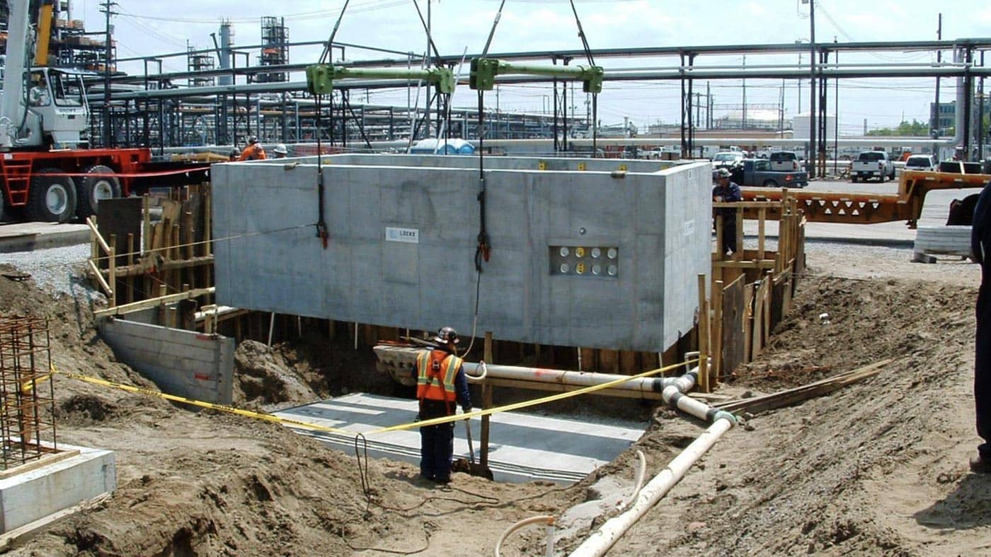
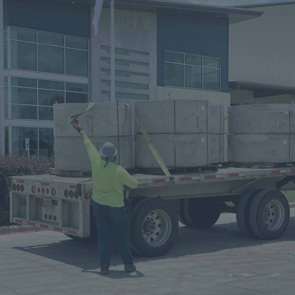
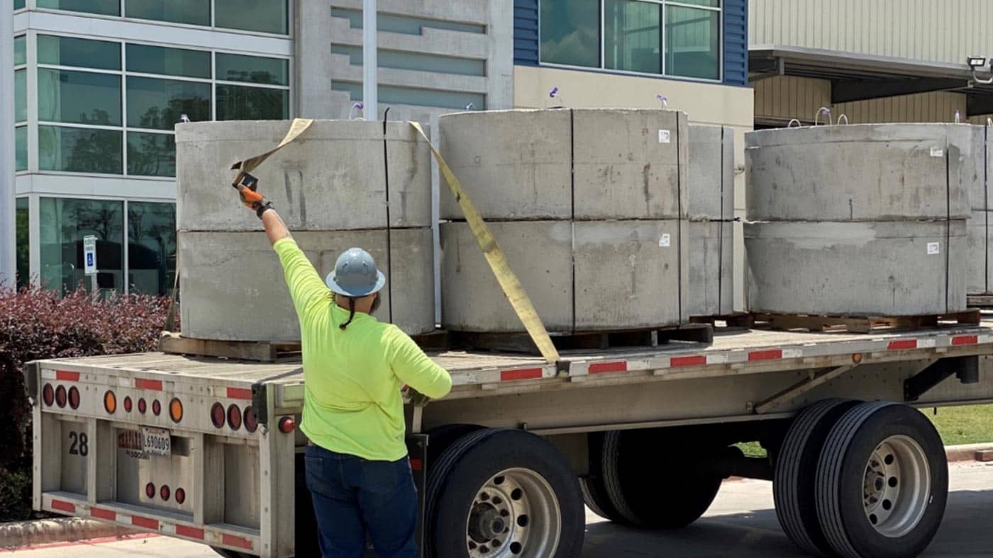
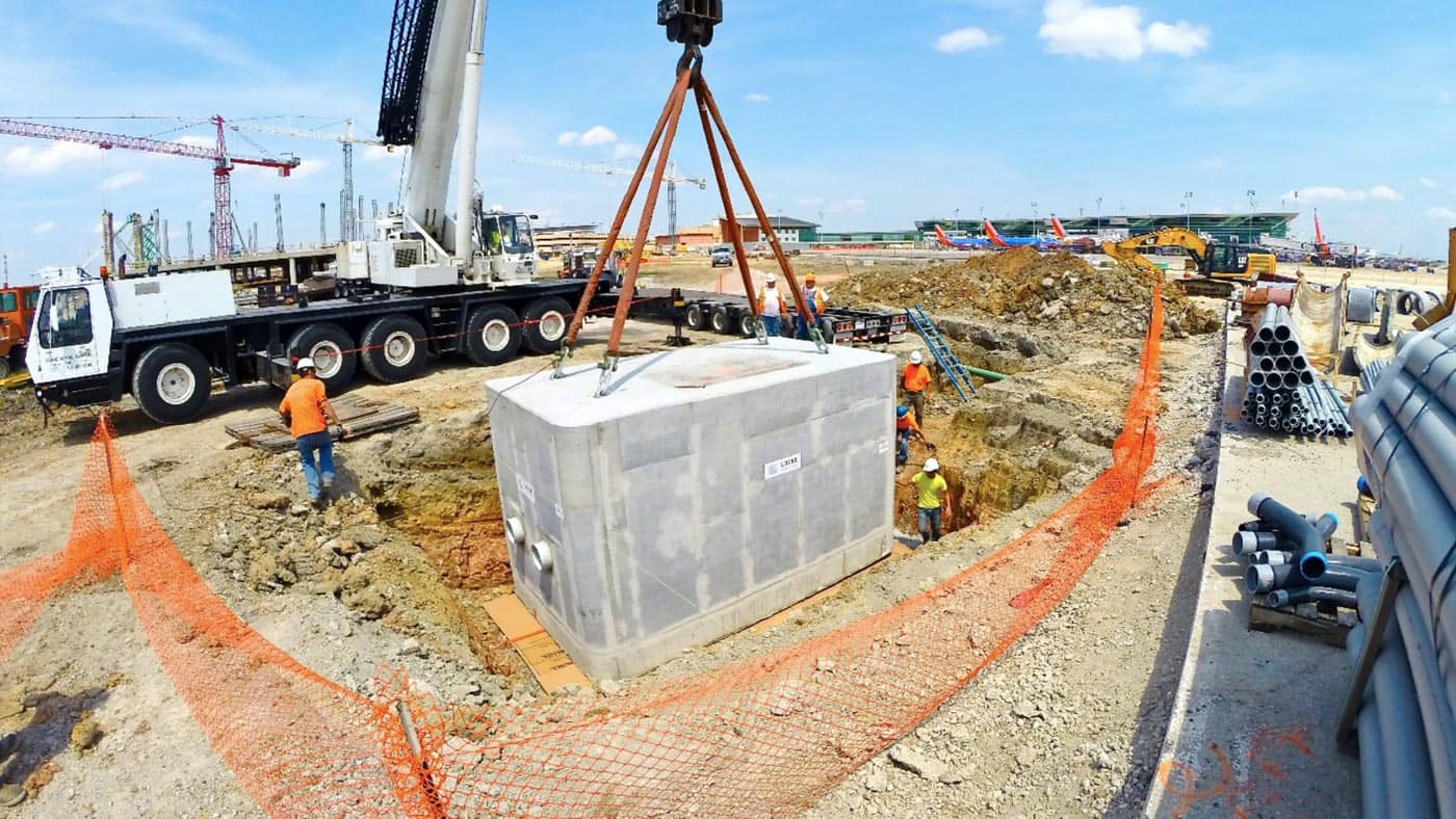
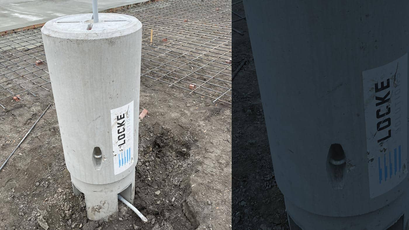
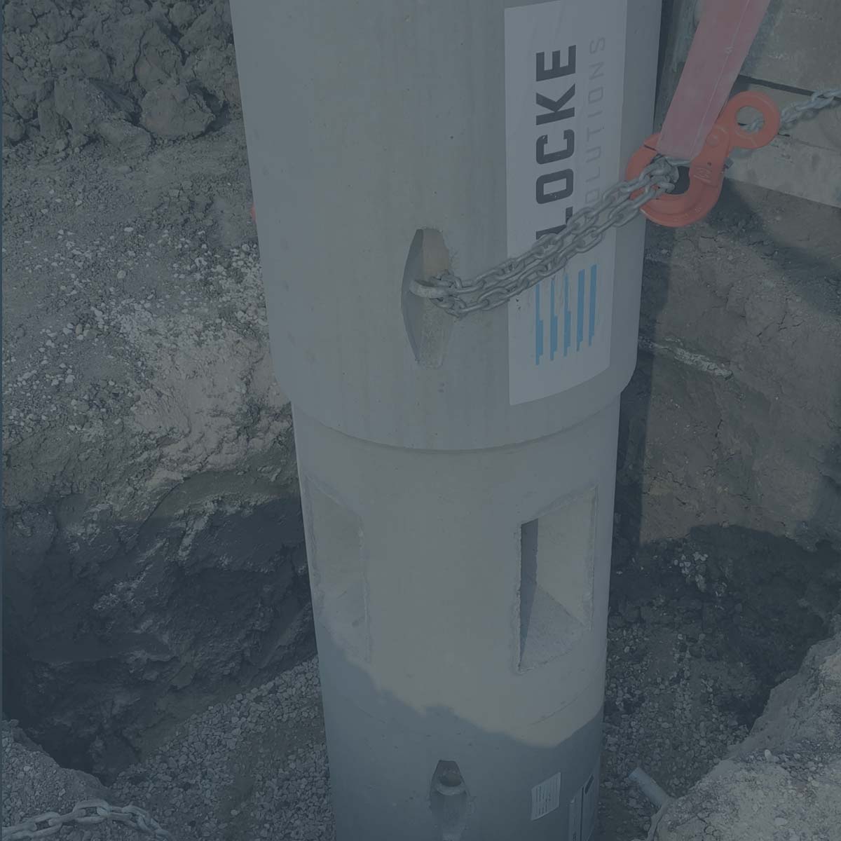
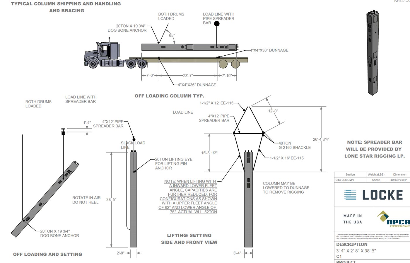
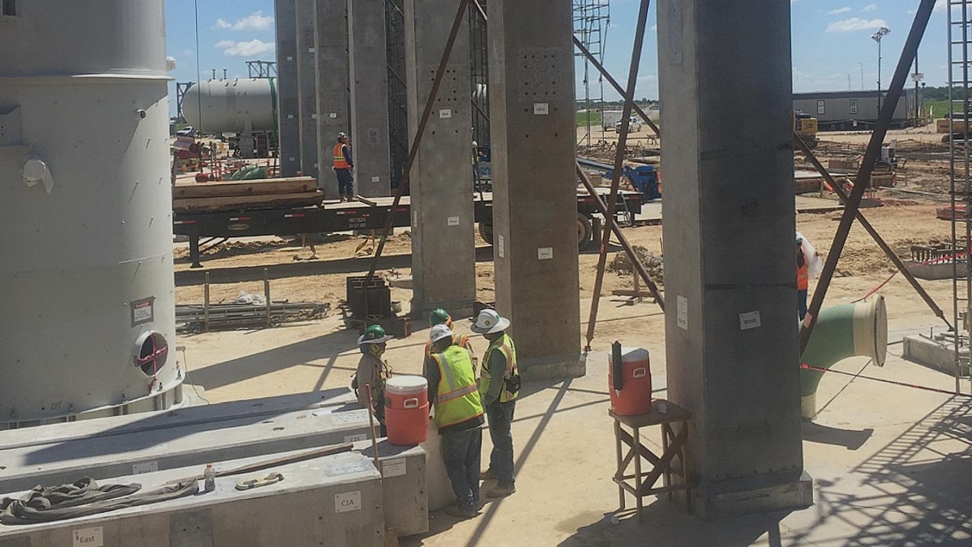
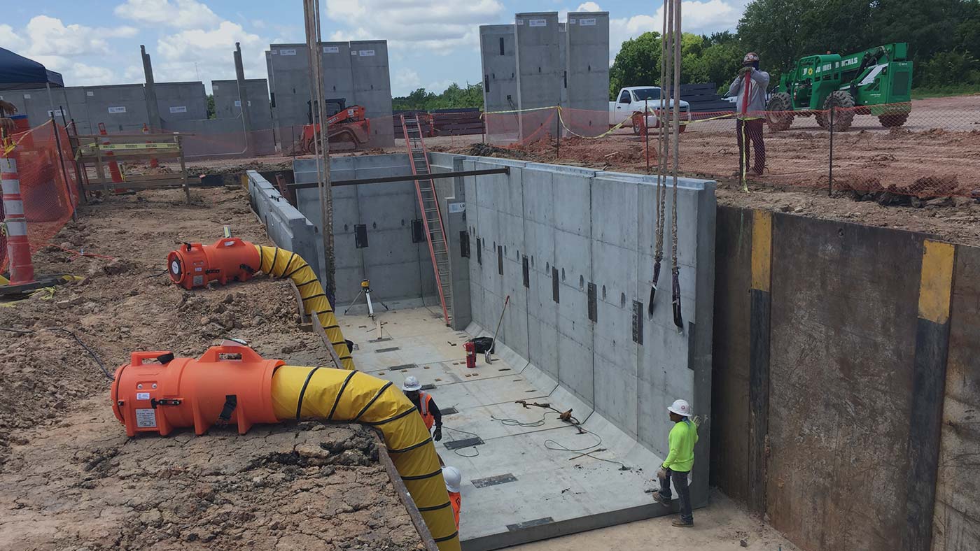
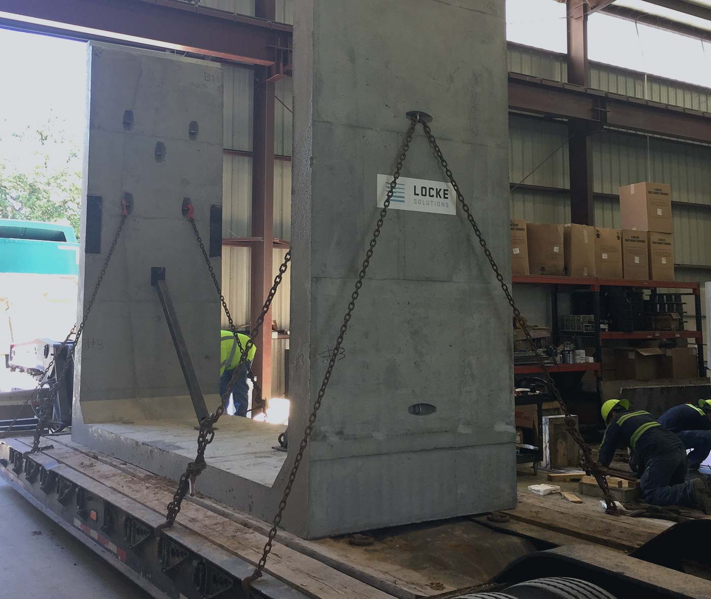
- Setting the precast concrete structure with an excavator or crane to the final position. More information about safe offloading of precast structures can be found here (https://lockesolutions.com/safe-methods-for-offloading-handling-precast/).
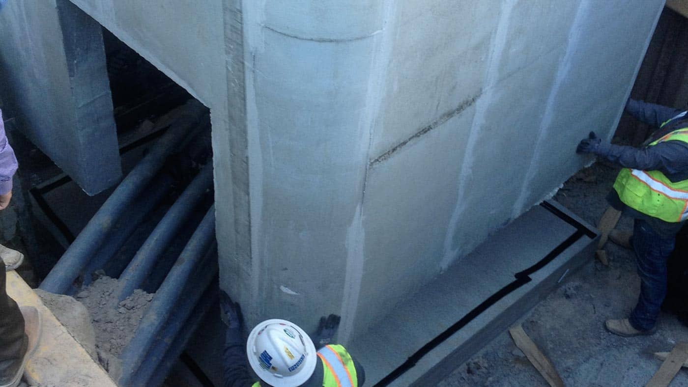
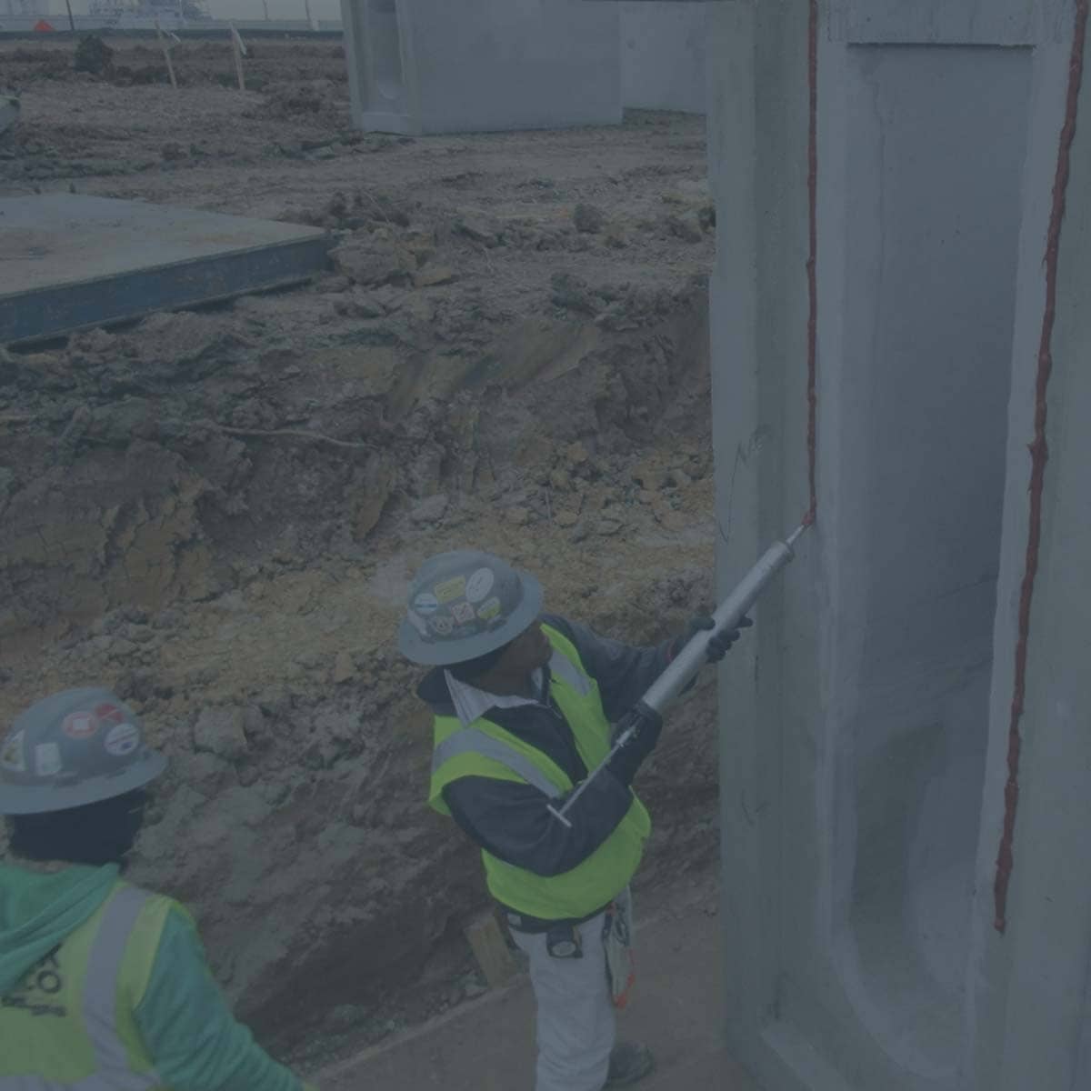
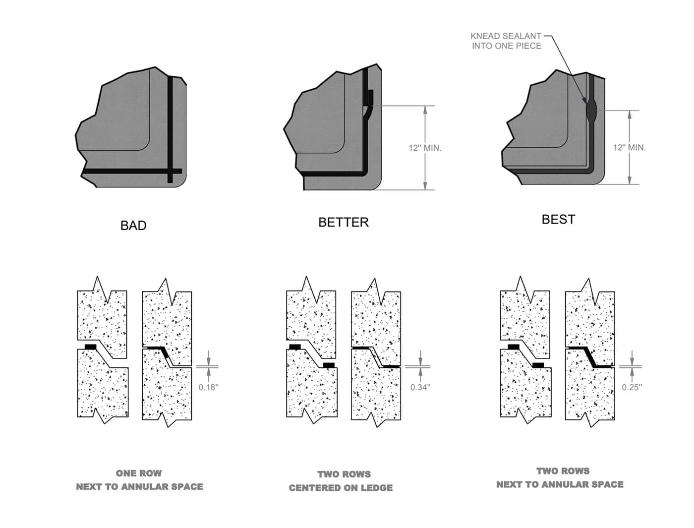
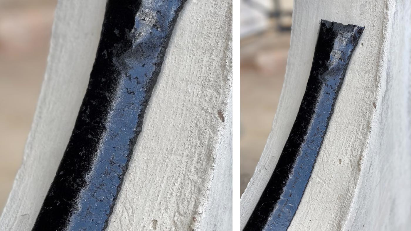
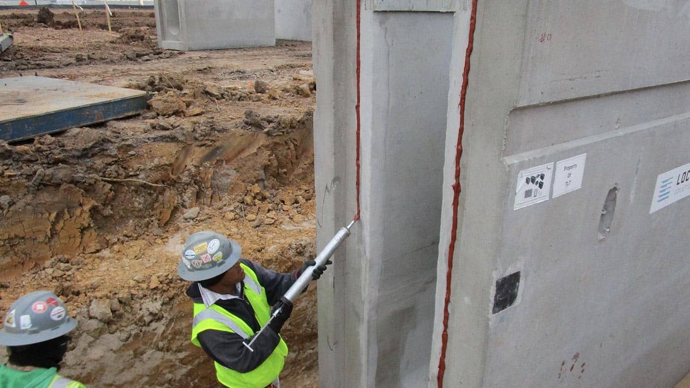
- With structures having multiple sections, joint sealant or grout is applied between sections to ensure a proper seal. More information on typical joint sealants and installation can be found here (https://lockesolutions.com/precast-concrete-joint-sealants/).
- Lastly, because the precast structure is already fully cured to design strength, backfilling can take place immediately. The backfilling process typically takes place in several layers of backfill anywhere from 6” to 18” at a time while compacting each layer during the process.
Although the installation steps for precast concrete structures appear minimal, much of the fabrication process is being done offsite prior to installation. Here are the typical steps in the manufacturing process that will not be seen on the job site.
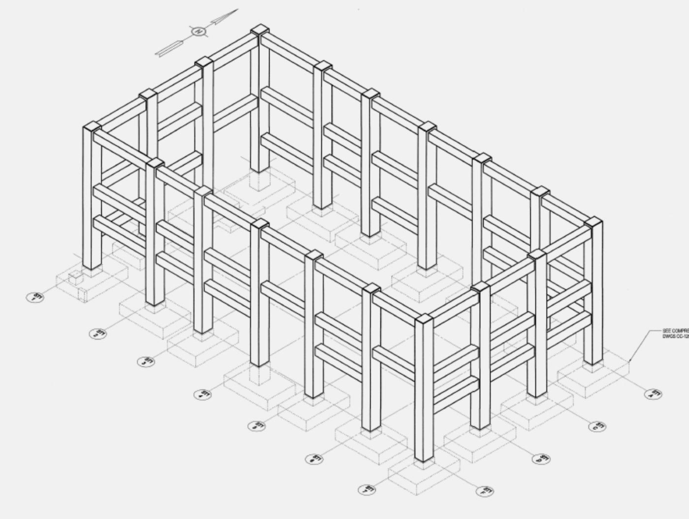
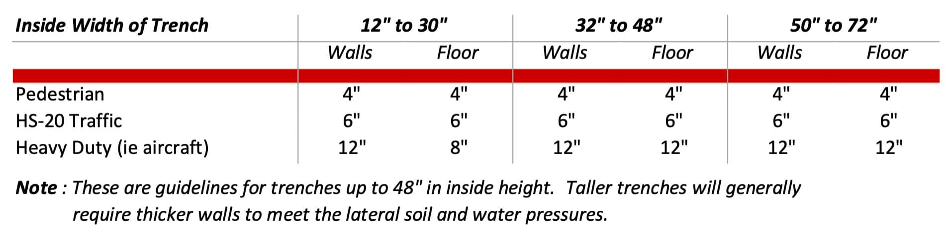
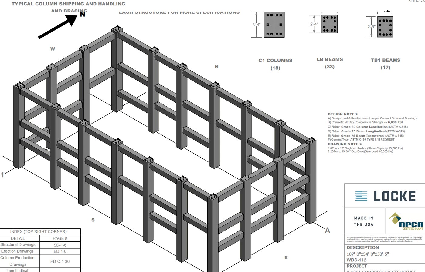
- First, structural design analysis is performed to determine the necessary wall thicknesses, steel reinforcement size and spacing, and concrete strength to meet the project requirements.
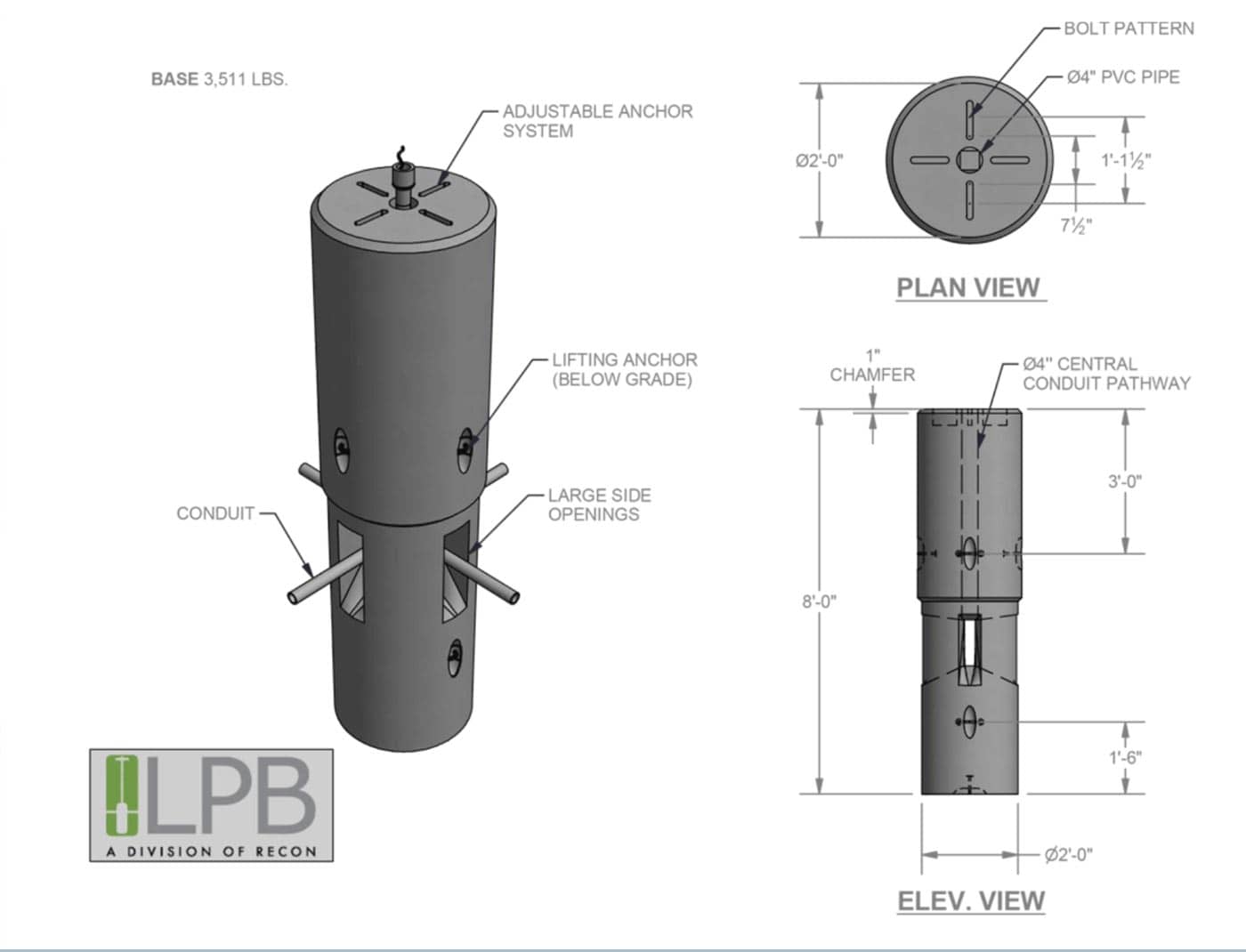
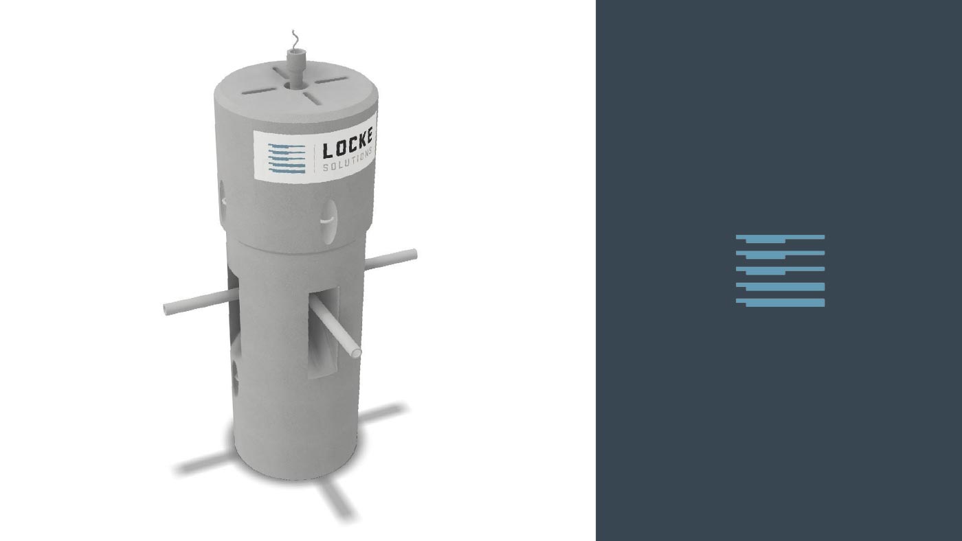
- 3D models are created using CAD software. These models are used to ensure no conflicts occur between all items cast into the structure.
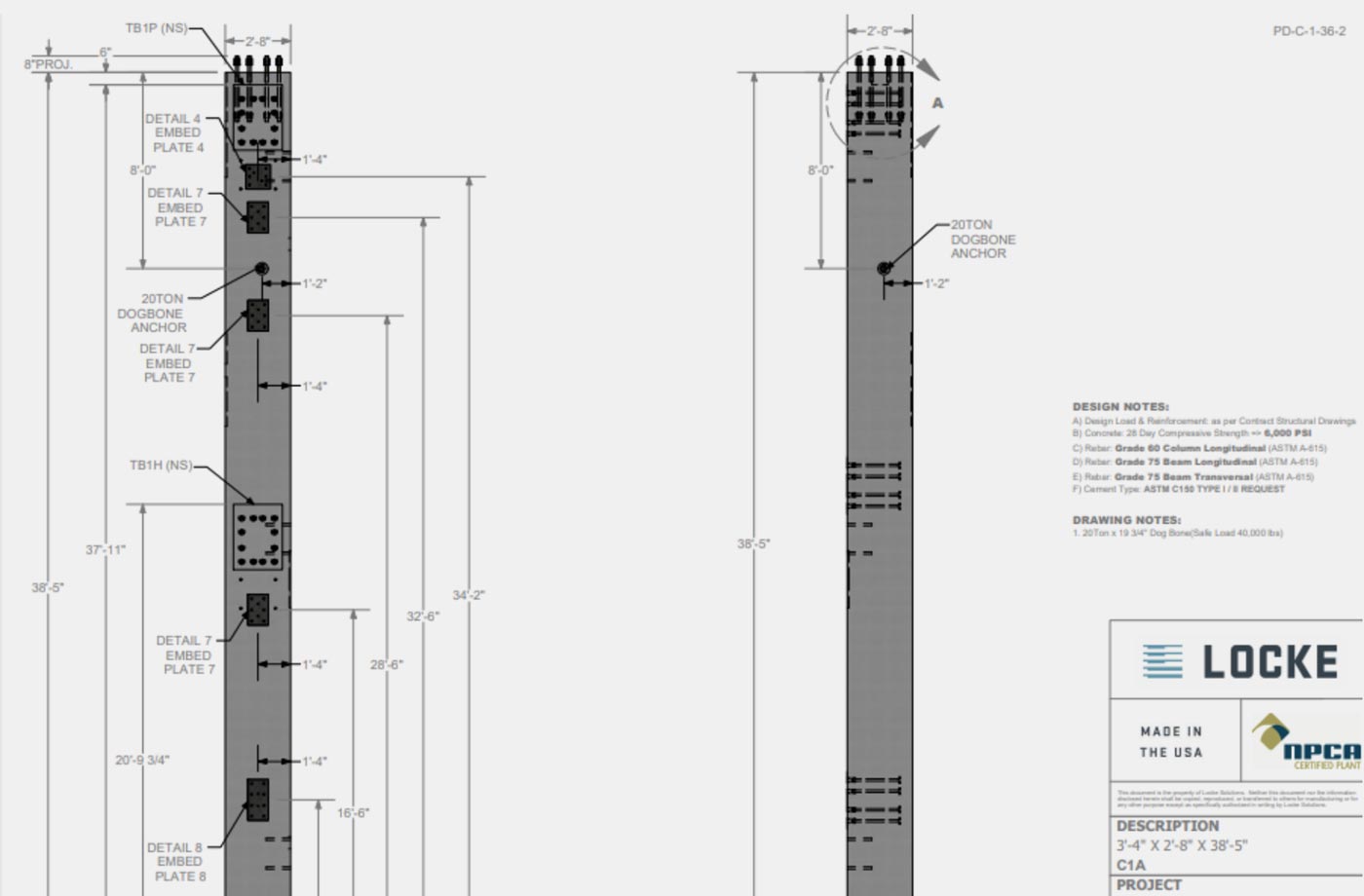
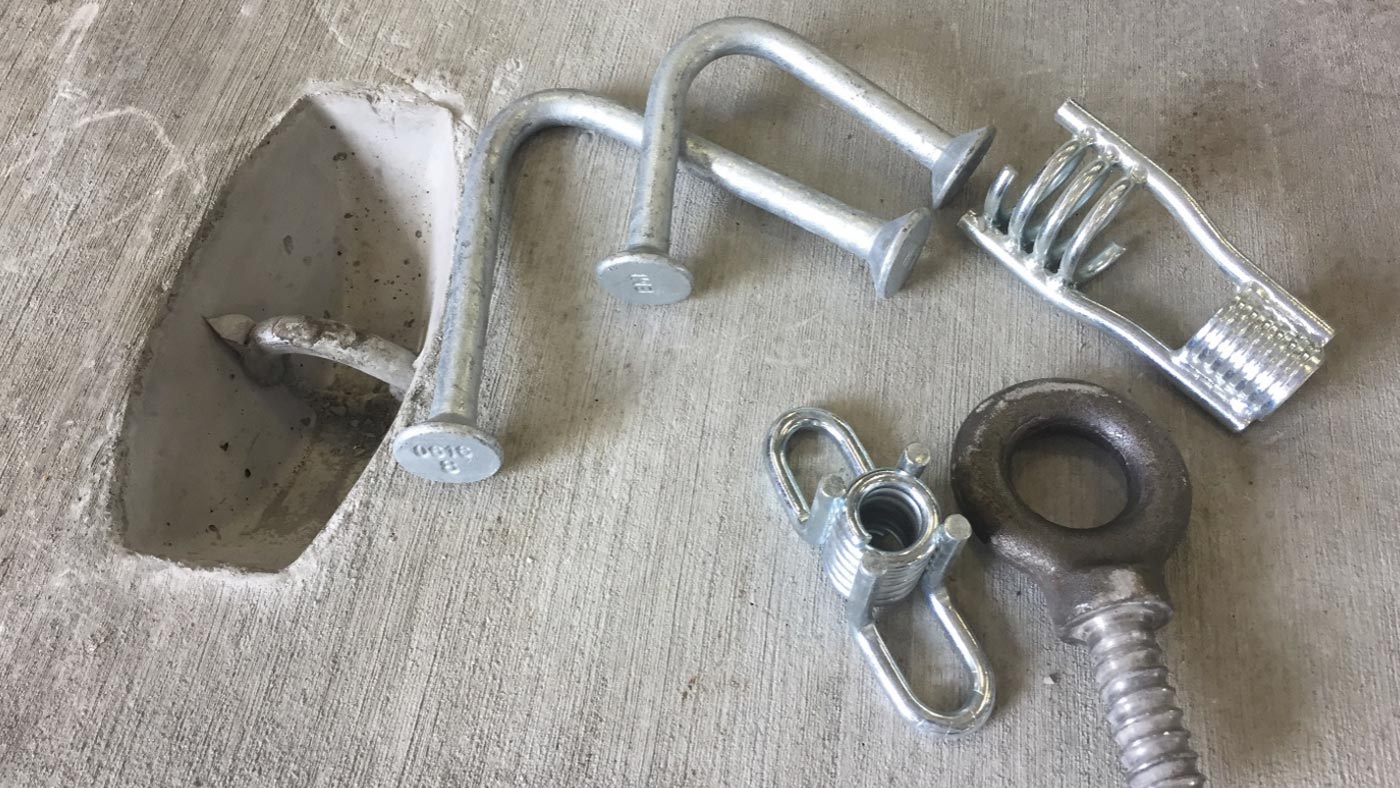
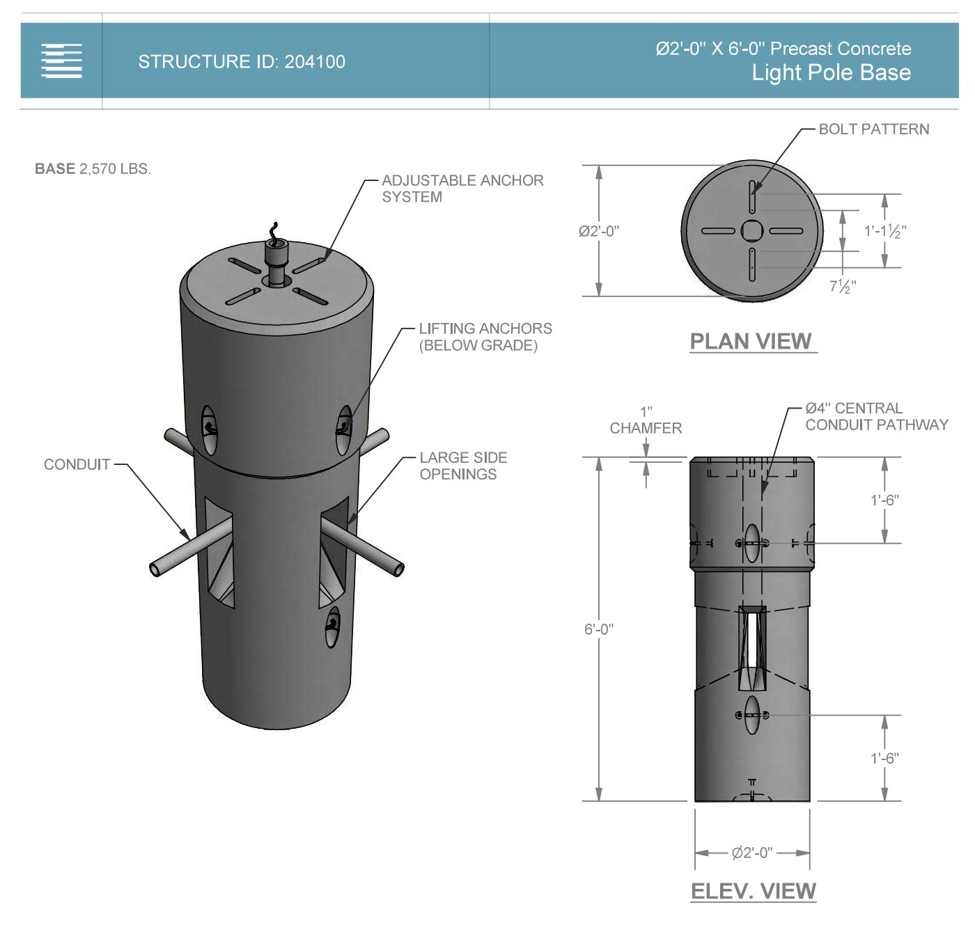
- Production drawings are created from the models and detailed to show all necessary dimensions and specify proper lifting anchors, rebar placement, and other items such as cast-iron manhole rings that may be cast into the structure, for example.
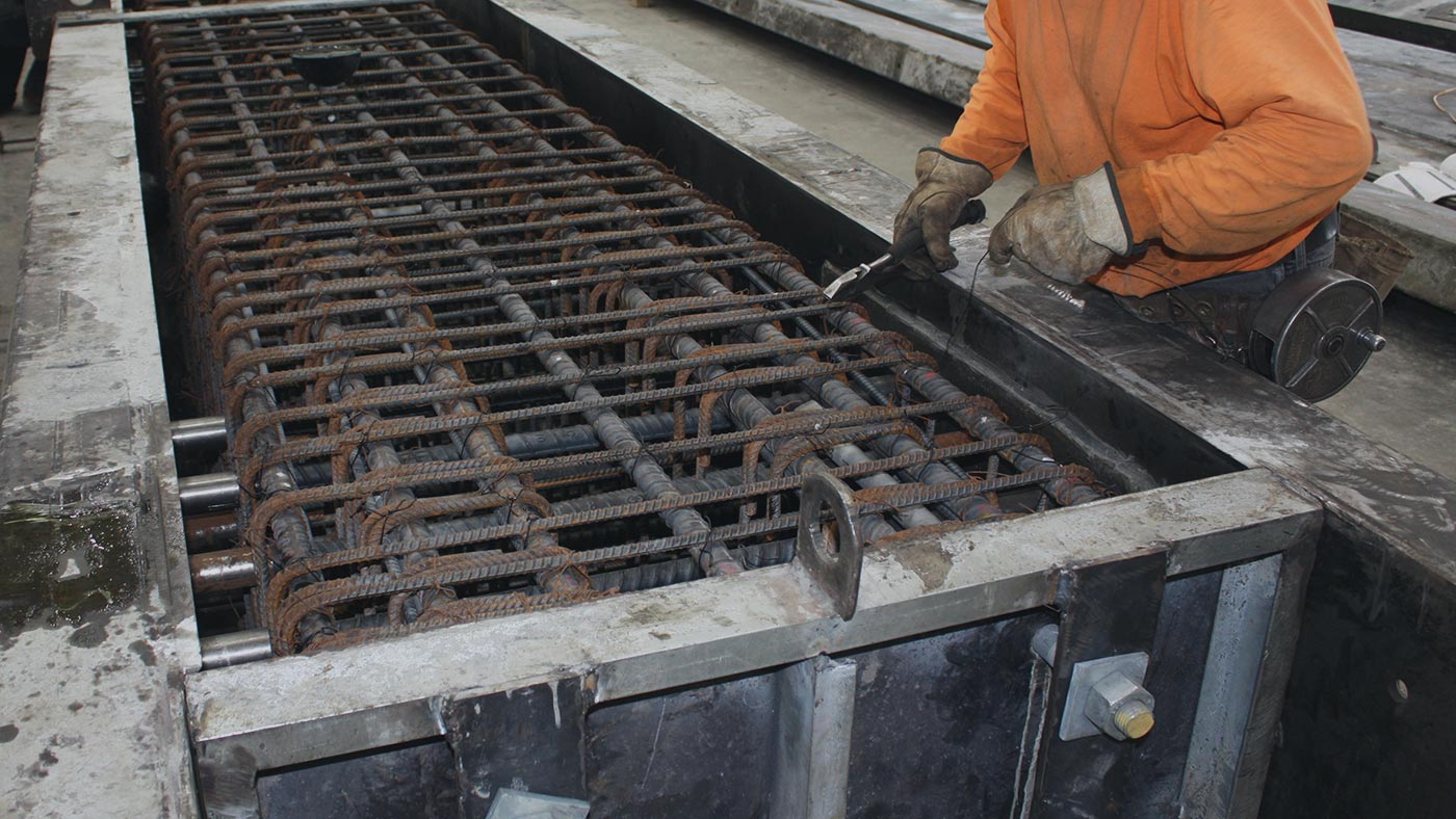
- After approval of drawings, the steel reinforcing cage is fabricated by the precast manufacturer in advance.
- Quality Control technicians inspect the steel reinforcing cage for proper rebar size, spacing, and overall dimensions. After inspection, the rebar cage is tagged to indicate its approval for production.
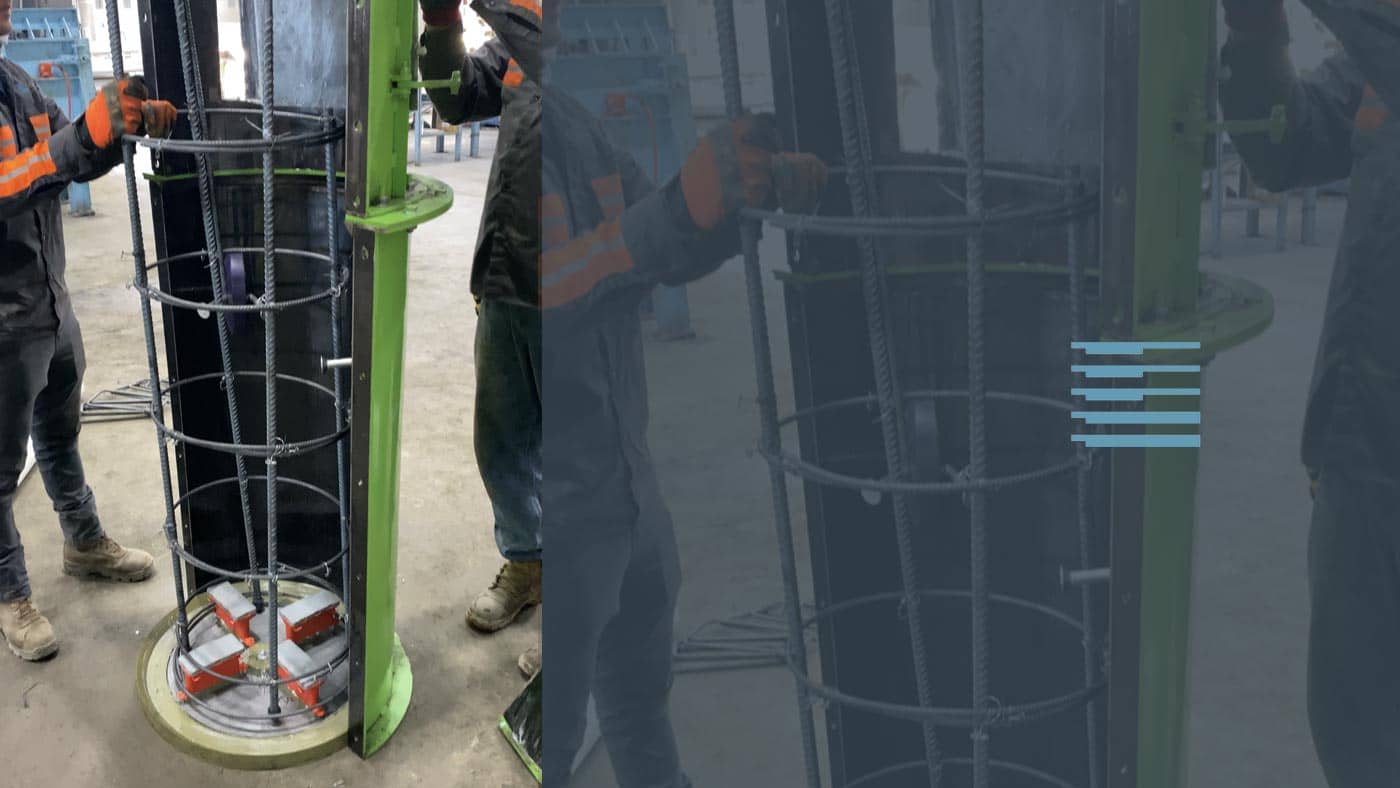
- Formwork is set up with steel, aluminum, or wood molds and inspected by Quality Control for cleanliness and proper dimensions and bracing.
- Next, the rebar cage is placed in the mold and spacers are added to ensure the rebar cage cannot shift in the mold during concrete placement.
- A pre-pour inspection is then performed by Quality Control to ensure all dimensions are still accurate and all rebar and items cast into the concrete are secured and in the correct position. Once the inspection is complete, Quality Control then tags the mold to indicate its approval for concrete placement.
- Concrete is then batched in the manufacturing facility when needed and placed in the mold.
- During the concrete batching process, ACI-certified Quality Control technicians take a sample of the concrete and perform fresh concrete testing including temperature, air content, unit weight, and slump/spread tests. If there are any deviations to the concrete results, a new batch of concrete is mixed. Concrete sample cylinders are also taken during this process.
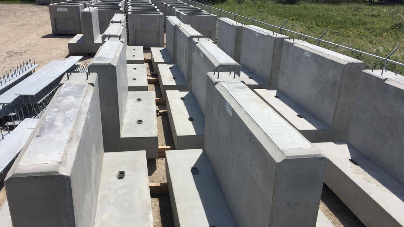
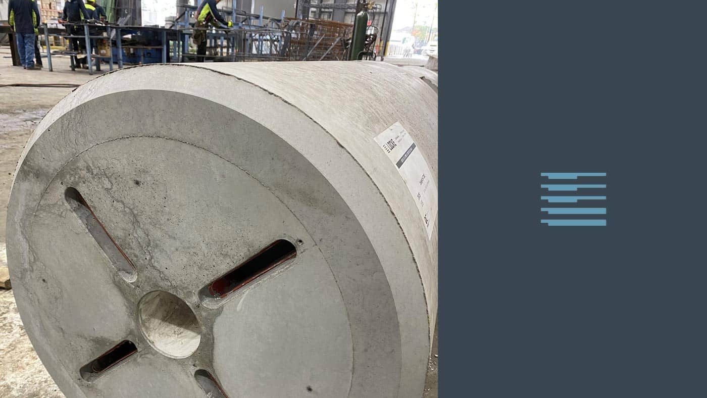
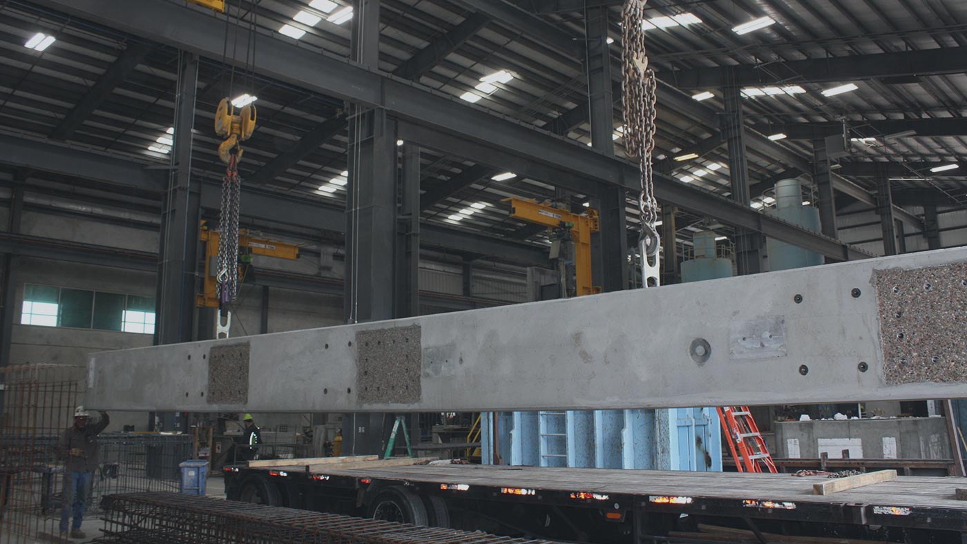
- After the concrete has cured and met strength requirements, the structure is de-molded from the formwork. Quality Control then performs a post-post inspection to verify the dimensions of the structure are still within project tolerances. During this process, the structure is labeled with information of the project, weight of the structure, and the date of production. After the inspection is complete, Quality Control marks a sign of approval on the product, and it is then transferred to the laydown yard.
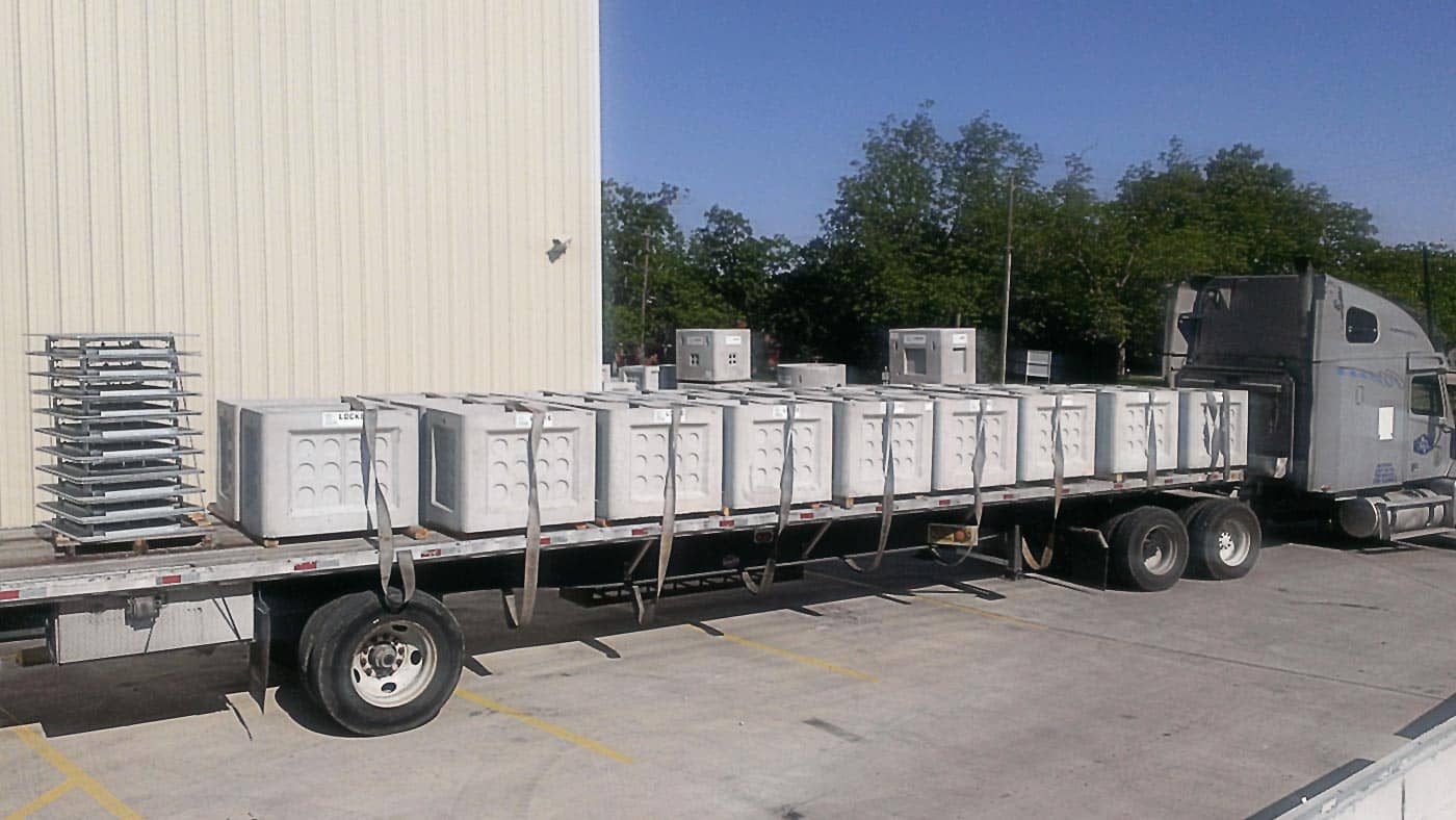
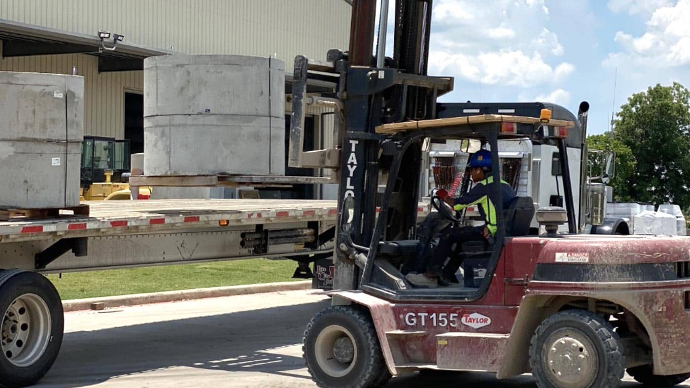
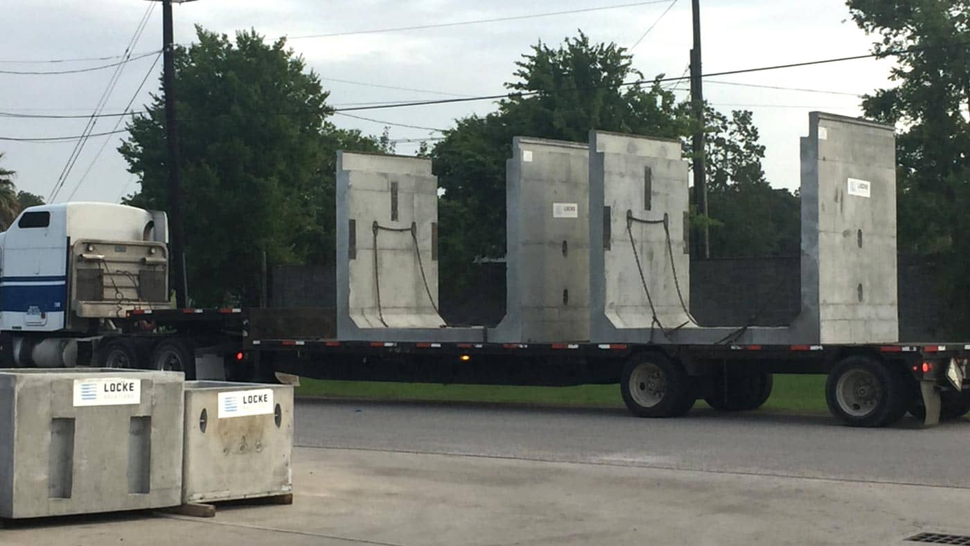
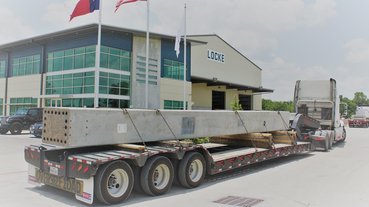
- Lastly, the precast manufacturer communicates with the contractor on the best delivery day and time and coordinates trucking to deliver the product to the job site. More information on shipping best practices can be found here.
- Quality Control will perform compressive tests on the sample concrete cylinders and will retain these strength results to ensure the concrete has met the design strength requirements of the project. The inspection reports, concrete cylinder tests, and material certifications are kept on file and available to the contractor if needed.
Advantages of Cast-In-Place
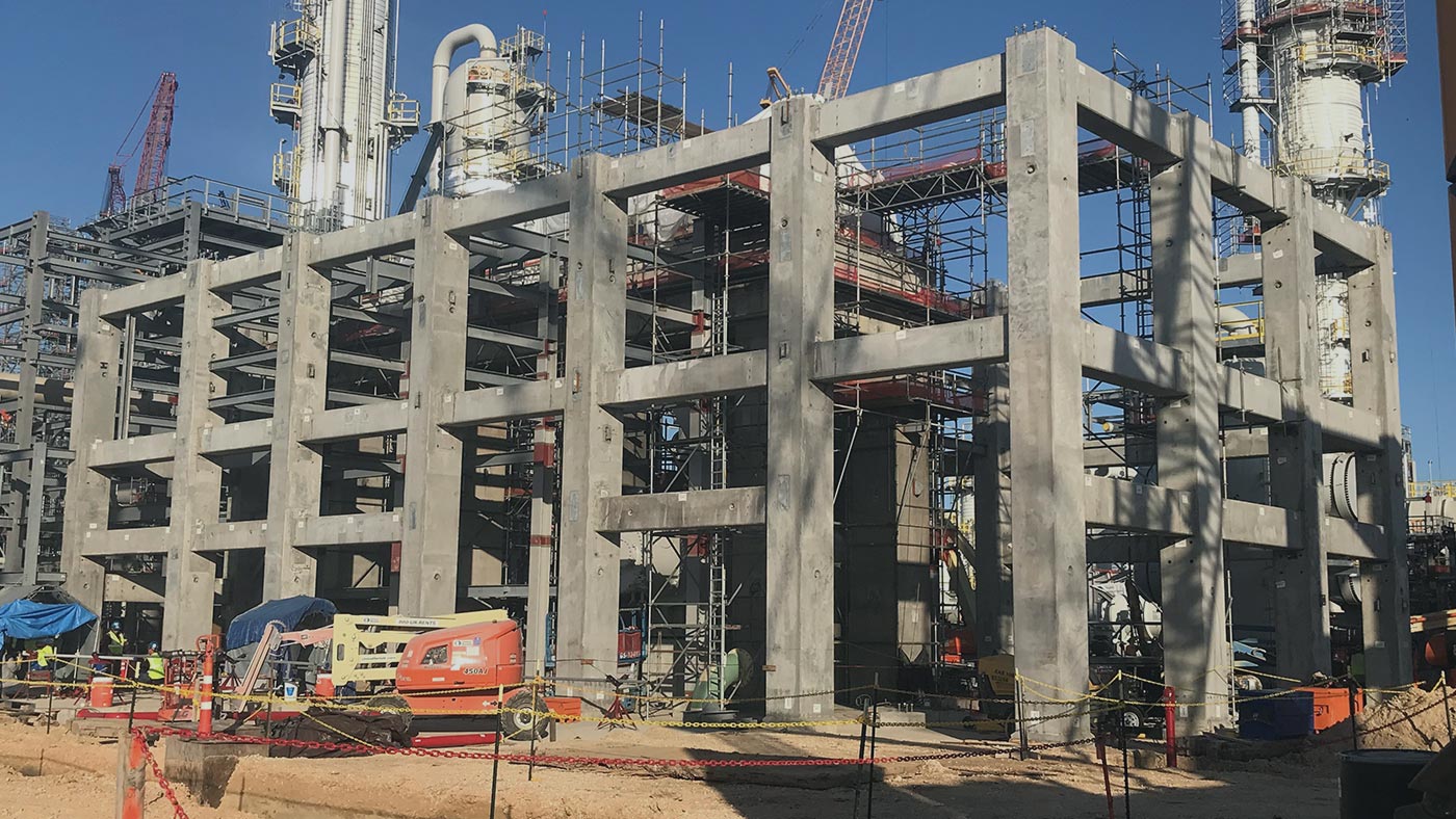
Cast-in-place is often the first choice when pouring foundations or slabs and it is often used when building large bridge column supports and roads. It can also be used when building walls and roofs. Because precast structures are already fabricated prior to arriving at the job site, they are not as adaptable as casting a structure in-place. If a precast structure is brought to a job site and the dimensions are not compatible with the prepared area, then the precast structure may have to be modified or not used at all.
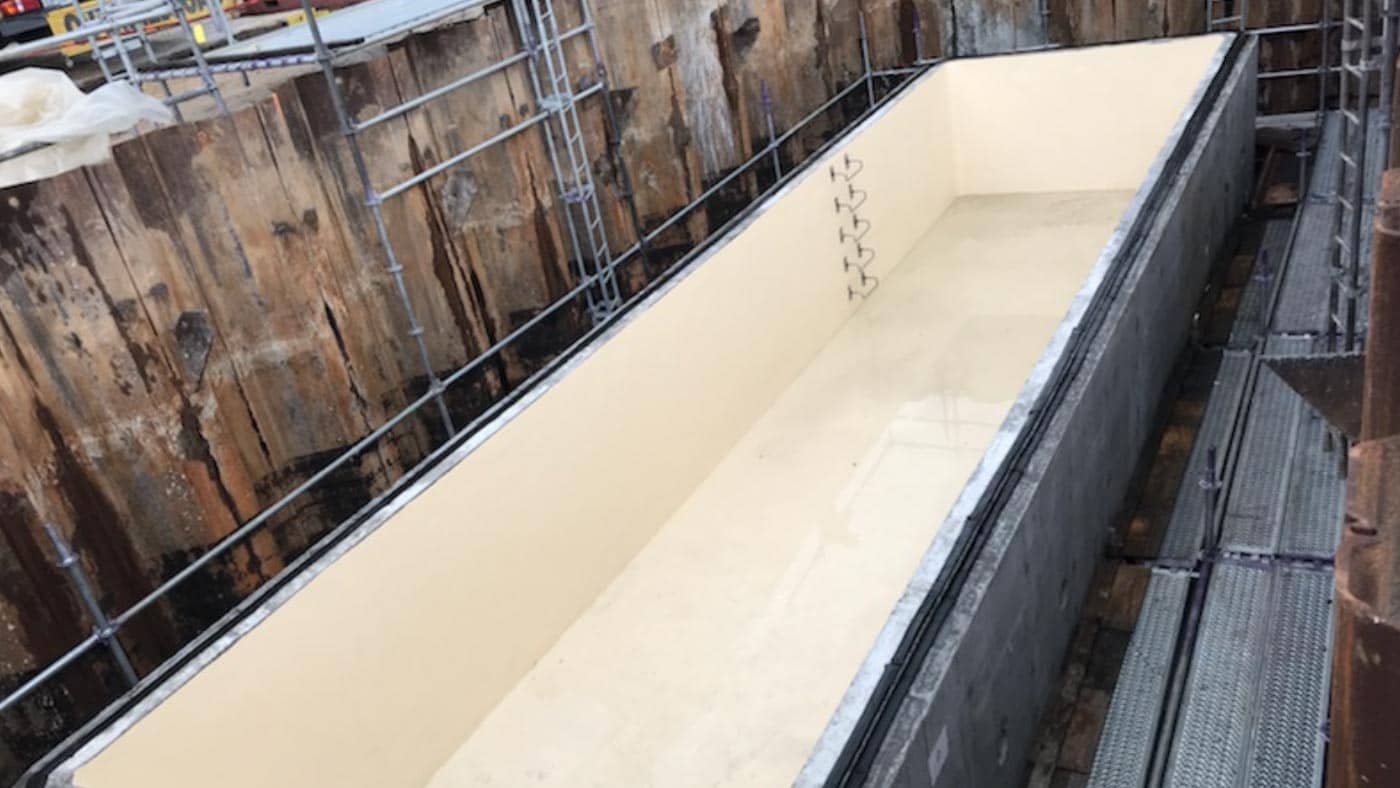
In other situations, there may be concerns with having joints within a structure, such as a containment sump with hazardous liquids. Precast structures often require multiple sections and joints within the structure. Although there are many joint sealants and liners to provide a watertight structure, the cast-in-place method can oftentimes avoid this concern.
Precast concrete structures can also be challenging to handle because they can be heavy and extremely large. For this reason, cranes or larger equipment are typically needed to offload and place the precast structure into place. There is no need for this extra equipment in the cast-in-place construction process.
Casting structures in-place may also be more advantageous when working in a tight or restricted job site condition. It can be difficult to lift and place a precast structure when overhead obstructions are present or working inside a building or parking garage.
Other inherent challenges with the precast concrete construction method are discussed in more detail here.
Advantages of Precast
Precast concrete does have its advantages. One being that it is made in a controlled environment. This means more quality controls are present with concrete batching, dimensions, and inspections. Most precast manufacturers have certified technicians and engineers to monitor and aid the team during the production process.
Another major advantage with prefabricating any structures, including concrete, is the reduced delays brought on by bad weather conditions. Most precast facilities are indoors and will continue producing product even during bad weather conditions that will typically shut down a jobsite. During the installation process, the precast method may only take a few hours to install versus the cast-in-place method taking weeks or months. Particularly in regions with frequent rain events, precast can reduce a project duration by months minimizing the time an excavation is open. This means less water pumping, less mucking out, and less time renting safety equipment associated with open excavations.
Labor management is also greatly reduced when working with precast structures. Often the cast-in-place method requires multiple trades and inspectors to be managed throughout the process. This means more safety orientations, training, management oversight and HR management that is avoided with precast construction.
![]()
Conclusion
The construction methods utilizing precast concrete and cast-in-place concrete both serve important roles in construction and they both have their advantages and disadvantages. The customer should always assess their needs to determine which option best suits their project.
Stay tuned for our next article.
We hope this article was helpful. Please send in your questions to info@lockesolutions.com and we would be happy to help answer them.