achive.php: you are in the loop
slug: precast-concrete-joint-sealants
post_type:post

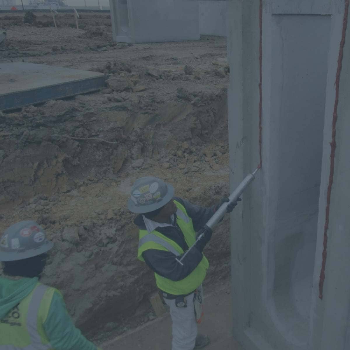
How do you seal up precast concrete joints and what are the most common concrete joint sealants used?

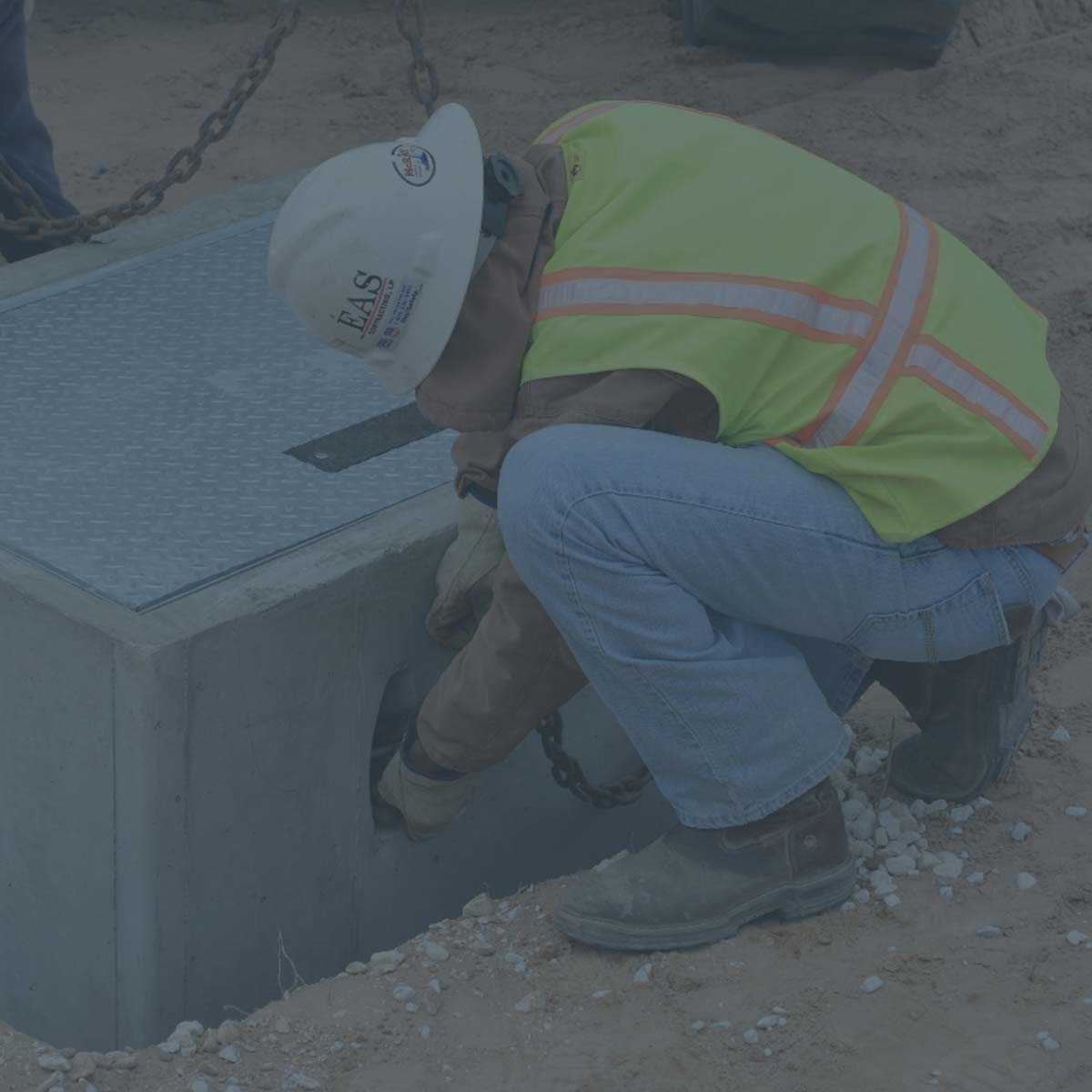
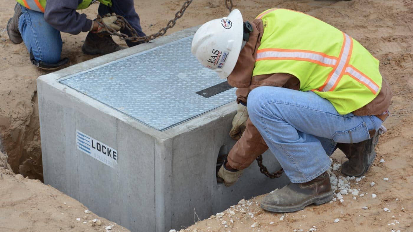
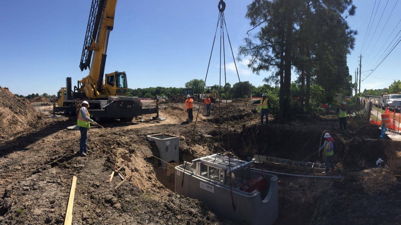
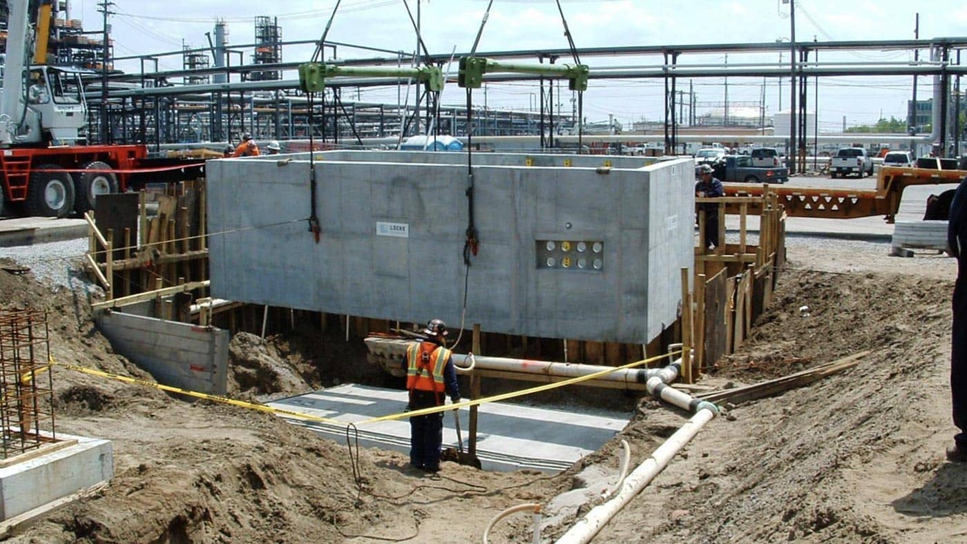
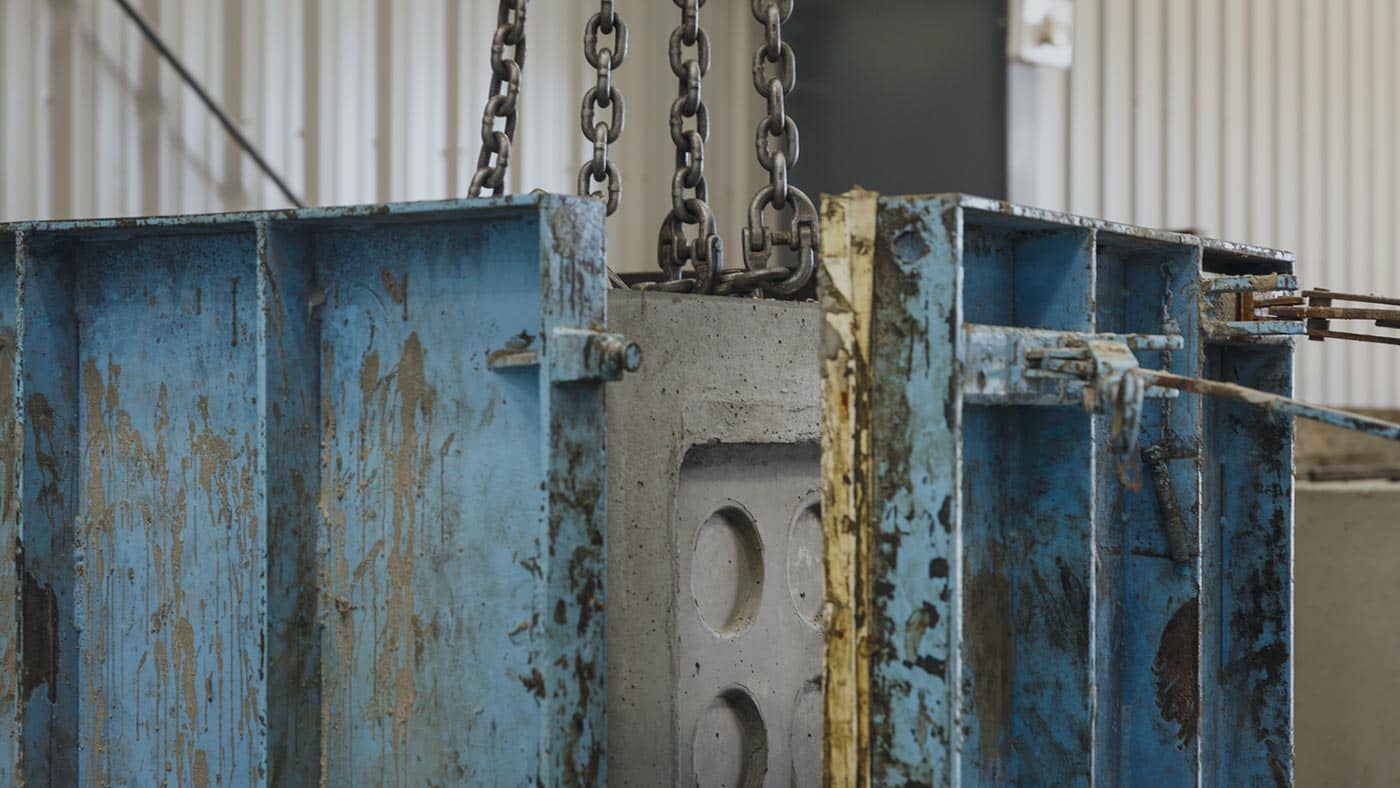
Manholes, Catch Basins, Sumps, Culverts, and Trenches are just a few structures that often require joint sealants. To ensure that the joints are properly sealed, it is important that the correct steps are followed and that the right type of joint sealants are used.

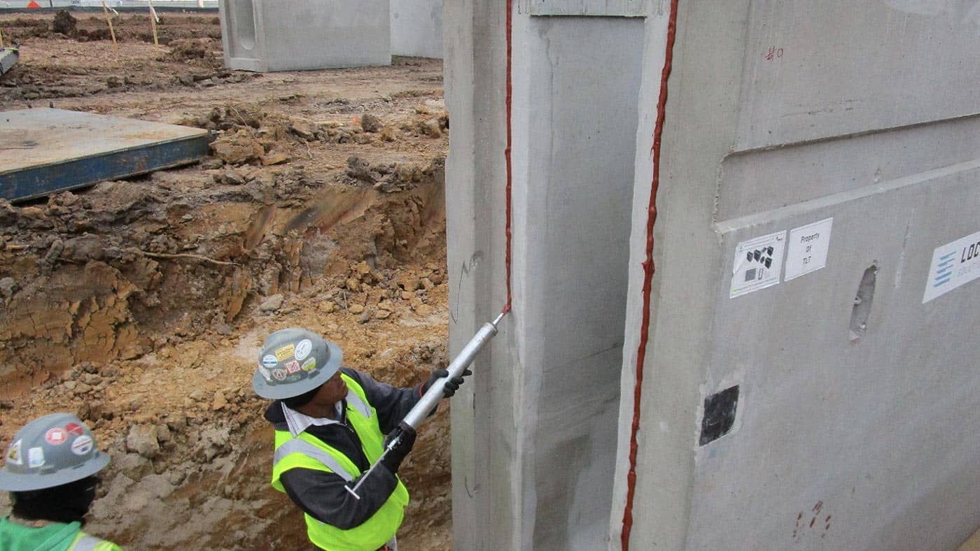
Before precast concrete joints can be sealed, it is important to check that the joints are properly prepared for the application of the joint sealant. It is crucial to ensure that the joints are level and completely clean and free of any dirt or debris. At this point, a primer may be used to help create a more adhesive bond between the sealant and the concrete surface. Once the joints are inspected, the application of the joint sealant can begin. 

“When sealing precast concrete joints, it is important that the joints are clean and completely straight. The sealant must also be applied properly to the joints. If this is done correctly, the structures will not leak, and this is the main goal with sealing precast concrete joints.”

-Andy Gemmill

BUTYL-RUBBER BASED SEALANT

Butyl-Rubber-based sealant is a popular precast concrete joint sealant as noted in ASTM C990 “Standard Specification for joints for Concrete Pipe, Manholes, and Precast Box Sections Using Preformed Flexible Joint Sealants.” It often comes in strips and has a sticky texture similar to the consistency of tar. Press-Seal, ConSeal, and Henry are companies that provide Butyl-Rubber-based preformed joint sealants meeting this ASTM C990 specification. 

Installation for Butyl-Rubber Joint Sealants

The two most common questions by contractors using this type of joint sealant are:

  1. Where should the preformed sealant be placed on the joint?
  2. What is the correct method for connecting the joint sealant to create a continuous seal?

Location: The most common joint profile where butyl-rubber joint sealants are used is the single offset shiplap joint as shown below. As you can see, there are several acceptable positions for placement of the sealant, but a good rule of thumb for other joint profiles is to place the joint sealant as close to the center of the joint as possible.

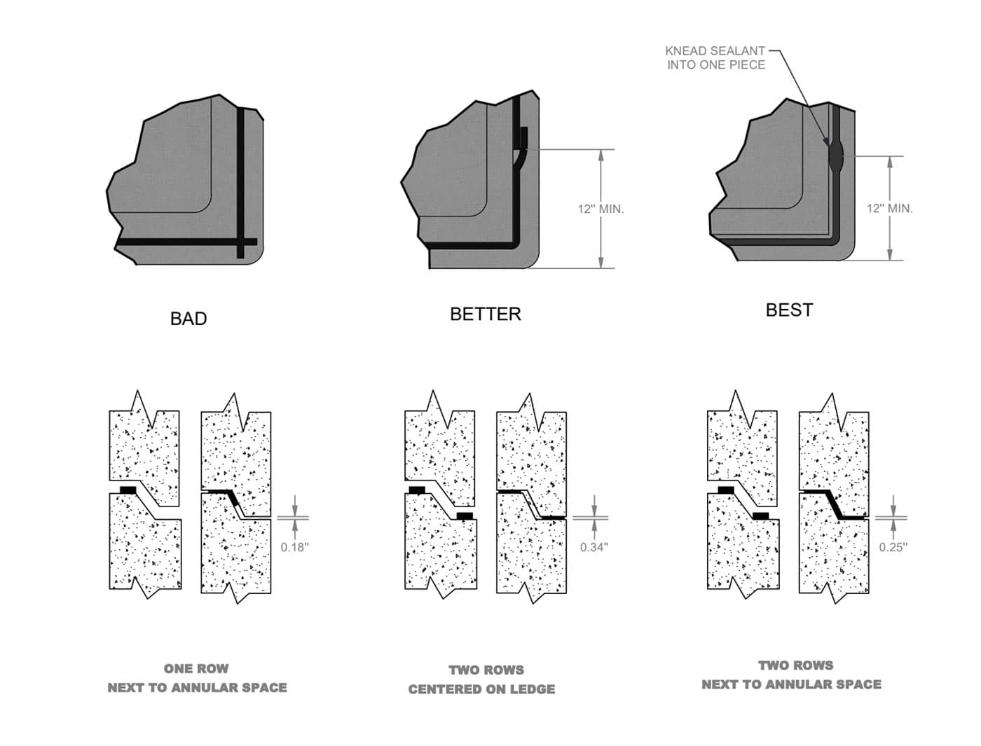
Connection: These butyl-rubber-based preformed sealants typically come in pre-cut rolls or strips and when placing on the precast structure, it will require multiple pieces. To prevent a gap in the seal along the joint at this connection point, it is recommended to connect the two sections by kneading the ends together and creating a similar cross-section profile at the connection. It is also recommended to avoid connecting two pieces of sealant at the corner of a structure.


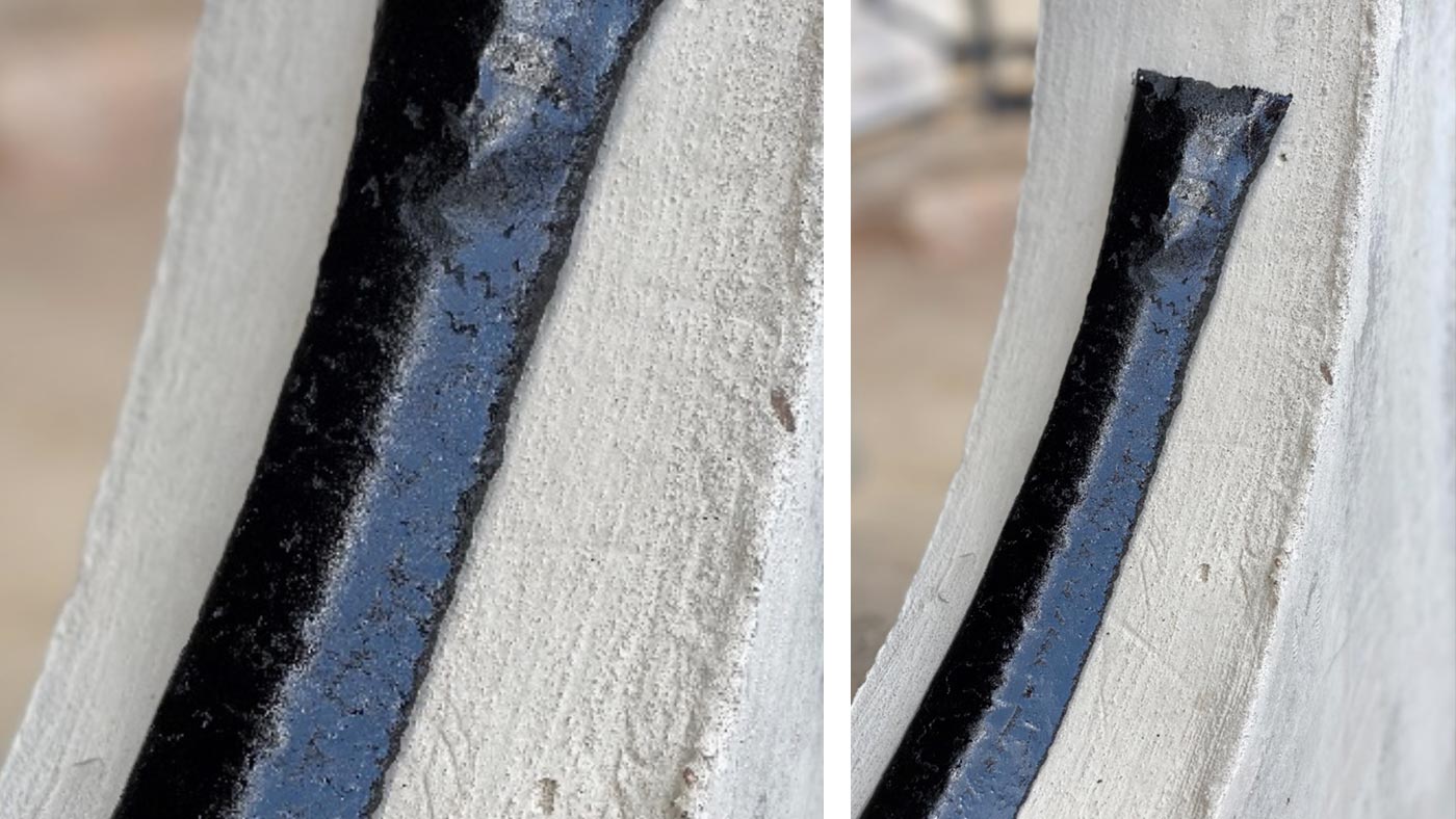
Installation of Sealant around a Corner


The outer wrapper on the sealant should be left on to keep it clean and prevent over-stretching while placing the sealant along the joint. Once the strips are in place, the wrapper may then be removed prior to placing the next precast section in place. After setting the precast sections together, the butyl-rubber sealant will compress, and it is normal for the sealant to slightly ooze out from between the joints. Depending on the ambient conditions, the rate of compression will vary, and it is recommended to wait about 10 minutes to allow the sealant material to reach maximum compression.

If the use of a primer is required before placement of the butyl-rubber sealant, several options are available including ConBlock SH, CS-50, and CS-75, all of these provided by ConSeal with different features.

  • ConBlock SH – this primer is applied in advance and developed to absorb into the concrete and react with the calcium hydroxide turning it into a hardened crystal.
  • CS-50 – a solvent-based liquid butyl primer applied in advance filling in the micropores of the concrete with rubber creating a great bond for butyl-rubber sealants.
  • CS-75 – a water-based adhesive primer that leaves a tacky surface applied at the time of sealing.

Butyl-Rubber based Joint Sealants:


HYDROPHILIC ELASTOMERIC JOINT SEALANT

Another type of joint sealant is a hydrophilic elastomeric joint sealant. Examples of this type of sealant include Sika’s SikaSwell and ConSeal’s CS-1900 providing a swellable waterstop to seal up precast joints and concrete construction joints. These sealants are provided in various forms and can be applied with caulking guns or placed as strips similar to the butyl-rubber preformed strips. The technology with these sealants provides a swelling effect of the sealant when it comes in contact with water creating a watertight seal in the connecting joints.

Hydrophilic Elastomeric Joint Sealants:


GROUT CONNECTION

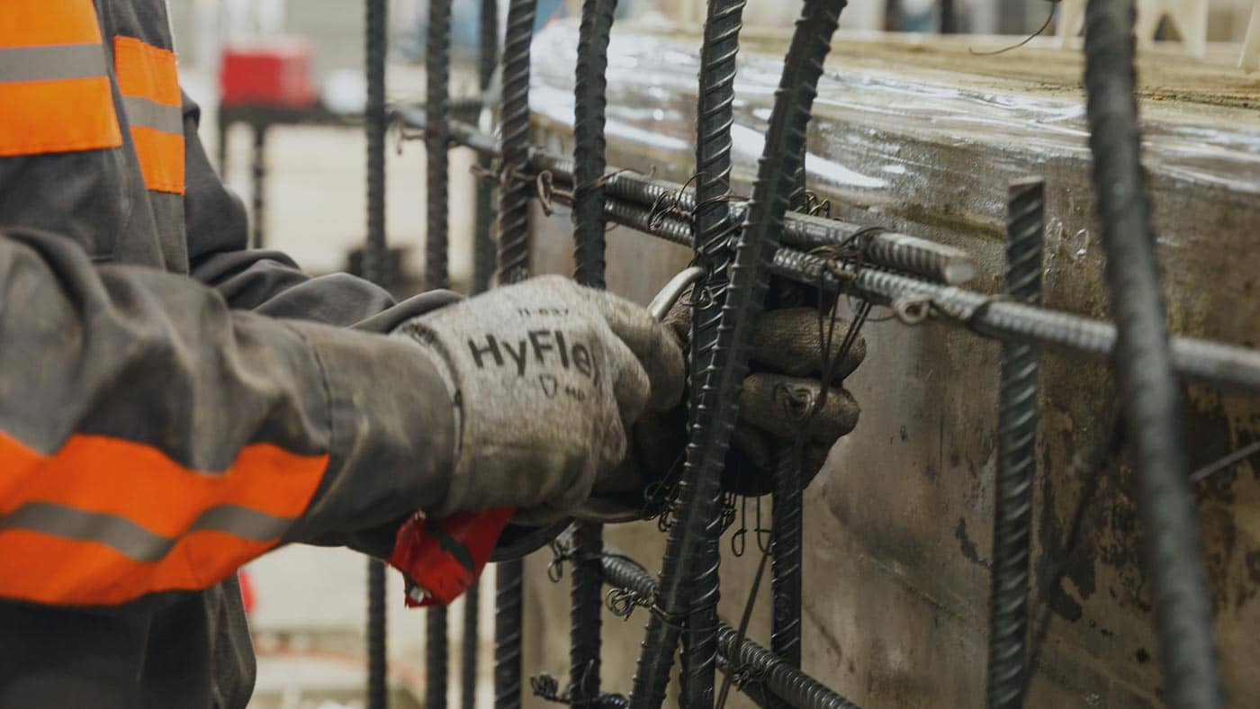
Joints between precast concrete sections are sometimes connected using a cementitious grout. Grout is a mixture of water, sand, and cement that is mixed and can reach compressive strengths of 6,000 to 10,000 psi at 28 days of curing. Often cementitious grouts are used to bed the joints between precast sections or to facilitate a structural connection with projecting reinforcing steel embedded into a pipe sleeve. Whether creating a bed of grout or pumping the grout into open cavities between precast sections, the joint should be prepared to remove all dirt, oil, grease, and other loose material that could prevent a strong bond with the grout. The joints should then be carefully aligned, joined together, and any excess grout that squeezes out can be wiped away.

There are numerous manufacturers of cementitious grout, but below is a shortlist of common materials.


FUEL AND OIL RESISTANT JOINT SEALANT

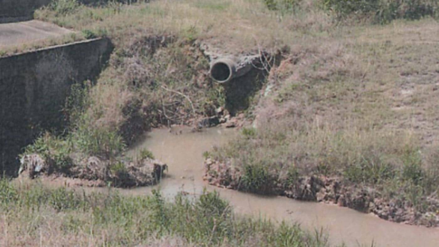
Occasionally there is a need to provide joint sealants able to resist certain chemicals such as fuels and oils. When working on industrial sites or dealing with stormwater or sump systems with potential hydrocarbon contamination, it is critical to pick the right joint sealant that can hold up to the potential chemicals. Each situation is different, but here are a few joint sealant products that can be useful in these situations.

Regardless of the chemicals you are encountering, more than likely there is a suitable joint sealant to handle the job.


Stay tuned for the next article!

achive.php: you are in the loop
slug: common-problems-with-precast
post_type:post

Precast concrete can present problems. However, there are proactive measures that can be taken and several solutions to combat many of these challenges.

Here are some of the most common challenges we hear associated with precast concrete structures:

  1. Sealing the Joints
  2. Shipping the Product
  3. Offloading & Rigging Concerns
  4. Preparation of Subgrade
  5. Lack of Flexibility
  6. Repairing Spalls or Cracks

SEALING THE JOINTS

Problems can arise with the sealing of precast concrete joints. Over time, joints can separate from one another which can compromise and weaken the structure. This problem can occur when joint sealants are not applied correctly. This usually occurs if the joint sealant instructions are followed incorrectly. If the joints are not properly prepared or cleaned prior to applying the joint sealant this can weaken the adhesion between joints and prevent the joints from properly sealing with one another. However, joint sealant problems are usually very preventable. If the joint sealant instructions are followed and all appropriate preparations are made prior to applying the joint sealant such as: ensuring that the joints are clean and free of any dirt or debris along with checking that the joints are properly formed to fit together correctly by conducting a dry fit or checking the alignment prior to the joint sealant application, then the application of precast joint sealants should be successful and problems with the joint sealants should not occur. See more about joint sealant options and installation in our article.


SHIPPING THE PRODUCT

Shipping precast concrete can be challenging and it is should be a coordinated effort between the manufacturer and job site contact. Precast concrete can be difficult to transport due to the weight and potential because of how large the structures can be. For larger structures, specialized trucking and various preparations could be needed to transport the structures. The greater the height, width, and weight of the structures, the greater number of arrangements that are possibly needed to facilitate the transportation. Structures over 8 feet 6 inches wide will require a permit. Structures that are over 14 feet wide require a permit and an escort. Structures that are over 16 feet wide will require a permit and two escorts. Precast concrete structures that are over a certain weight will also need a weight permit. For shipments taller than 13 feet, route inspections must take place and potential bucket lifts may be required to add in avoiding powerlines. The route will be surveyed to ensure it is safe for the structures to travel. Logistically, transporting precast concrete can seem challenging, but utilizing expert hauling companies who understand the DOT rules and who are equipped with the right trucks and trailers can make the delivery seamless. In the event the structure is too heavy, too tall, or too wide to be transported, precast designers can normally split the structure into multiple sections to reduce the weight or size of any individual precast section. There are several methods for creating structural connections between sections of precast in the field. This makes transporting these large structures possible and reducing the lifting capacity needed on site.  See more about shipping best practices in our article.


OFFLOADING AND RIGGING CONCERNS

Another challenge with precast concrete is offloading and properly rigging the structures. Normally, cranes or large equipment are needed to pick up and move the structures. As with any process involving cranes, there is a risk associated with understanding the capacity of the crane, rigging, and lifting devices. It is important that the correct rigging is utilized so that the structure is secure before lifting.

Improper shoring of an excavation can lead to catastrophic failures and should be inspected and engineered if necessary. In the event that a job site has overhead obstructions or there is a question regarding the shoring, it is a good idea to involve the crane company and walk the site before installation. For extremely large structures, lifting diagrams and rigging plans should be created by certified engineers to ensure the structure is lifted properly. Understanding how to correctly rig a precast structure, recognizing the lifting capabilities of the equipment and rigging devices, and knowing which equipment is most appropriate for each individual lift will facilitate a safer and more efficient offloading and setting process.


PREPARATION OF SUBGRADE

Preparing the subgrade is one of the most important elements of a successful precast concrete installation. Problems can arise if this is done incorrectly. A subgrade that is weak can settle incorrectly and shift the structure causing it to crack or sink. For example, if electrical cables are running through any of these structures while they shift underground, cables can break creating significant problems. The surest way to prevent this is to make sure that the subgrade is properly prepared for the structure. To do this, the ground must first be excavated correctly. Any unwanted debris or materials should be removed. By doing this, it will help to create a level and firm subgrade and it will help to stop the settlement or any shifting that would cause the concrete to crack. The subgrade must also be compacted and completely flat. When backfilling the subgrade, it is important to know the permissible backfill material. The backfill should be compacted and evenly distributed. Properly preparing the subgrade will help to ensure that the structure will stay in place and greatly minimize any issues from occurring. 


LACK OF FLEXIBILITY

Precast concrete can be challenging with its lack of flexibility once the structure has been built and delivered to the jobsite. Sometimes, precast structures are designed based on as-built drawings of what is expected to be encountered below ground. If a precast structure is built to tie into existing piping, there is the possibility of the existing piping to not be in the location expected, possibly rendering the precast structure useless.

To avoid this situation, partial excavations can be performed in advance to confirm the location of utilities prior to manufacturing the precast structure. Structures can also be designed utilizing thin wall knockouts, which are sections of the precast wall specifically designed to be thinner and allowable to break through the area needed. This provides more flexibility in where the location of the pipe penetration occurs in the precast wall.


REPAIRING SPALLS OR CRACKS

Precast concrete structures can sometimes get cracks or spalls. Structural spalls can occur from poor form construction, rough removal from forms, improper storage, early removal of the structure, and poor handling methods of the structure. There are three different types of concrete repairs: Structural Repairs, Cosmetic Repairs, and Architectural Repairs. Structural Repairs involve repairs around any lifting areas or structural connections. Cosmetic Repairs are used to repair the outside appearance of the concrete including filling in any bug-holes, honeycombing, or exposed rebar. Architectural repairs are more focused on high visibility architectural concrete requiring more stringent color and texture matching. 

Cosmetic repairs can be performed with a cement and sand mixture called grout and can be applied with a sponge float or a steel trowel. 

Structural repairs should be analyzed by a structural engineer and a detailed procedure should be developed to ensure a proper repair is completed. Often, an epoxy mortar or polymer-modified cement-based grout is used to repair structural cracks or spalls. In general, the damaged concrete should first be removed, then the surface prepared for the new repair material. Steel reinforcement should be cleaned and exposed and a primer should be used to create the proper adhesion between materials. Next, the new mortar should then be applied and left to set and cure. 

Using precast concrete in your construction process has its challenges, but if handled properly, the benefits to your schedule and installation costs can far outweigh these challenges. Consult with your local precaster if you have any other concerns or questions on your next project.


Stay tuned for the next article!

achive.php: you are in the loop
slug: shipping-precast-products
post_type:post

Best Practices for Shipping Precast Concrete Products… Small to Mega Large

Transporting precast structures can be an involved process and it requires careful coordination between the manufacturer and job site. Here, we will discuss how transporting these structures is made possible.


WHAT PROCESS TAKES PLACE BEFORE A PRODUCT CAN BE SHIPPED?

Before a structure can be loaded on the truck for shipment, there are several steps that must first take place. The product first must be inspected by Quality Control to make sure that the product is complete and needs no additional work. Once the product has been inspected and signed off by Quality Control that it is ready for shipment, Quality Control will alert the project manager. The project manager will then notify the transportation manager. Once the transportation manager is informed that the product is ready to ship, there are several duties that they will perform prior to the product’s shipment. First, they will create a delivery ticket. The delivery ticket will contain information that includes the shipment date, the trucking company that will ship the product, the load number, site contact address, and the ticket number. It will also contain the sales representative’s name and the customer purchase order number. Details about the structure itself will also be on the delivery ticket, such as the weight of the structure, the crane needed and details for the rigger. Four delivery tickets are then printed out. One is for the forklift driver so that they know which product is being loaded and shipped. Another is for the manufacturer to keep. Two tickets will be given to the driver. One ticket for the driver and one ticket for the customer.

Signatures are required from the forklift driver, manufacturer representative, Quality Control, transportation driver, and field representative for the product. The manufacturer’s transportation manager will also communicate with the transportation company to let them know which type of truck will be needed to ship the precast structure. Smaller structures can be easier to ship where larger structures will require more coordination and can involve different trucks or larger trailers to accommodate their size and weight. Structures that are over 8 feet 6 inches wide will require a permit. Structures that are 14 feet wide require a permit and an escort. Structures that are 16 feet wide will require a permit and two escorts. Precast structures that are over a certain weight will also need a weight permit.

For shipments taller than 13 feet, route inspections must take place and potential bucket lifts may be needed to avoid hitting any powerlines. The route will be surveyed to ensure that it is safe for the structures to travel. In the event the structure is too heavy, too tall, or too wide to be transported, precast designers can usually split the structure into multiple sections to reduce the weight or size of any individual precast section. The transportation manager will also contact a crane company to ensure that the correct number of cranes are at the job site. It is crucial to ensure that the crane has the capacity to lift the structure. For extremely large structures, lifting diagrams and rigging plans will be created by certified engineers to make certain that the structure will be properly lifted. How much reach is required from the crane is also an important factor. The manufacturer’s transportation manager will also coordinate the times that the trucks will arrive to pick up and transport the structures. They will also relay to the customer when the structures will arrive at the job site. Once all necessary preparations have taken place, the focus can then shift to loading the structures for shipment.

“We try to focus on loading the trucks in a timely manner so that they can make it to the job site on time. It is also important to make sure that any additional materials that are needed for the structure are loaded on the truck.” -Noe Castro, Transportation Manager at Locke Solutions


LOADING THE PRECAST FOR SHIPMENT

Precast structures are typically loaded by using a forklift, crane, or gantry. The structures are usually loaded on “dunnage.” The dunnage is a material that protects the product during shipment. Wooden pallets are commonly used as dunnage for precast structures. The transportation driver will communicate to the forklift driver on the loading placement of the structures. Depending on the size and weight of the structure, different sized trailers will be needed. Larger and heavier structures will need trailers with more axles to support and distribute the weight. It is important to be cautious and vigilant when loading precast structures. All who are involved in the loading of these structures should be dressed in proper personal protective equipment. A distance of 10 to 15 feet should be maintained from the forklift driver at all times when the structure is being lifted and then loaded onto the truck. Once the structure is loaded onto the truck, it will need to be properly secured. 

Structures are typically secured with chains or straps. Chains are often used for tall and heavy structures and straps are used for heavy and longer structures. The larger the structure, the more strapping will be needed. Once the straps are laid over the structure, they are fed through a lever and tightened until they are secure. 


FINAL INSPECTIONS

Final inspections should take place once the product is loaded onto the truck. As important as it is that all product is loaded onto the truck, it is equally important that any joint sealants, eye bolts, or miscellaneous items that are needed for the installation of the structure are loaded on the truck with the product. This should always be checked. Once these steps are completed and the transportation driver has the delivery tickets, the product is ready to be shipped to the job site. 


PRECAST MADE EASY

With coordinated efforts and clear communication, shipping precast concrete is made easy. Once the transportation driver arrives to the job site, the delivery ticket must be verified before the structure can be offloaded. Now that we know how to load and ship precast concrete, how do we offload these structures?


Stay tuned for the next article where we discuss offloading precast concrete.

achive.php: you are in the loop
slug: precast-light-poles
post_type:post

Every parking lot and city walkway are littered with light poles illuminating and creating a more inviting, safer space. Most people take it for granted and only notice the light poles when they’re absent creating a dark and precarious feeling at night. But if asked, the contractors installing those light poles will probably tell you how much of a pain it is to build this relatively unnoticed feature. And it’s not the actual light pole that is difficult to install, it’s the concrete base that anchors this light pole that creates so much coordination and effort.

Some parts of the country have discovered the relatively unknown secret of prefabricated concrete light pole bases, also known as precast concrete bases.

The traditional process of constructing concrete light pole bases in the field consists of drilling an excavation, placing formwork or cardboard tubing to create a round shape extending a few feet above grade, fabricating and placing a rebar cage, fabricating and securing conduit or openings for electrical wiring, and setting a template to maintain the exact spacing and vertical alignment of specific anchor bolts. At this point, a third-party inspection is typically required to ensure the proper reinforcing steel is used and placed in the correct position, the excavation and formwork have been correctly established, and finally, the anchor bolt and conduit positions are properly placed and secured to prevent any movement during the concrete pour.

Once the light pole base setup has been confirmed, ready-mix concrete is scheduled for delivery. Getting the 80,000 lbs ready mix truck close enough to the light pole base can be challenging, but once ready, the concrete placement beings and a geo-tech inspector is typically required to be onsite to take concrete samples during the pour. After the concrete has been placed and the concrete has cured, typically 7-10 days, the formwork or cardboard tubing needs to be removed and the light pole base needs to be patched and cleaned up to meet aesthetic expectations. All in, this process can take anywhere from 7 to 14 days, and that is assuming no downtime due to rain events or scheduling conflicts with the inspector, geo-tech technician, concrete and electrical trades, or ready-mix concrete delivery. It is a lot of work and coordination for a simple light pole base.

LPB set out to make this process easier. These precast concrete light pole bases can be made in advance and stocked to be ready when the customer needs them. The patented bolt pattern system allows for varying bolt patterns to determined onsite to fit exactly with the pole being attached.

This simple system changes the whole schedule and process for installing light pole bases. Not only does it simplify the 7-14 day process down to one day, but it also leaves the owner with a better quality pole foundation. The LPB’s are built in a controlled factory environment with high-strength concrete and constant quality control monitoring throughout the manufacturing process.

The contractor can control the schedule of installation and finish in a fraction of the time while virtually eliminating the risk of weather or inspection delays…all at a lower installation cost and headache factor. The LPB is delivered cured to strength, consistent, and clean with no need for additional aesthetic touchups.

Locke Solutions has recently partnered with the LPB as a licensee for the patented concrete light pole base system.

Recon LPB Precast Light Pole Base

It is not a surprise as there is a natural fit between Locke and LPB as both companies have a culture and purpose revolving around making life easier for our customers. LPB has taken the cumbersome process of constructing concrete light pole bases and turned it into a simple and quick step in the project.


Precast Light Pole Base Product Information

achive.php: you are in the loop
slug: light-pole-bases
post_type:post

Precast concrete Light Pole Bases are pre-engineered, pretested and manufactured in a controlled environment.

Precast Concrete Light Pole Bases provide a fast and easy way to install light poles up to twenty-five feet in height and in some cases taller.


We have partnered with LPB and their proven universal bolt system allowing us to stock pre-engineered units.


Light Pole Base Features:

• Accommodates Light Poles up to twenty-five feet tall
• Adjustable anchoring system for bolt patterns ranging from 7-1/4” to 13’-1/2” in diameter
• Pre-engineered and pre-tested light pole bases are 24” diameter.
• Light Pole Bases are designed for multiple conduits from all directions
• Other sizes available upon request
• The future of light pole bases

Minimize Your Project Time:

• Stocked and available for when you need it
• Fast and easy installation
• Less weather dependency
• Less manpower is needed


achive.php: you are in the loop
slug: compressor-platform-project
post_type:post

Locke Solutions recently manufactured the concrete column and beam structure for two compressor station platforms for a polyethylene expansion project for Total Petrochemicals near Houston, TX.  The total project consisted of 42 columns and 120 beams with individual sections weighing as much as 53,000 lbs.  Locke’s design team worked hand-in-hand with the contractor, Bo-Mac Contractors, and the engineering group with McDermott/CB&I to convert the original cast-in-place design to a precast construction method.  The goal was to drastically improve the schedule duration of the installation and to provide a safe working environment to manufacture this concrete frame with the tightest of tolerances.

Locke’s design team developed hundreds of drawings to detail each individual column and beam and show the unique placement of embed plates, anchor bolts, lifting anchors, steel reinforcement locations, and diagrams for lifting and installation.

The concept of prefabricated products has continued to gain favor as contractors and engineering firms are trying to find more efficient and quality methods of construction.  Not only concrete, but other materials have seen success with prefabrication methods including steel, piping, and electronic components…all benefiting from the advantages of offsite fabrication in controlled environments prior to being installed on the job site.

One of the benefits of fabricating these elements in advance is the ability to stage products and plan for delivery and installation when weather conditions are favorable.

The result is a structure built within a factory-controlled environment with zero safety incidents and laser tight tolerances, all contributing to shorter installation time and less risk of weather delays.

achive.php: you are in the loop
slug: personalizing-precast
post_type:post

At Locke, we take pride in the relationships we create through the products we build. Though we do have some products readily available “on the shelf”, we primarily create custom pieces for our clients by solving their technical problems in order to create a design that meets their needs.

We consider this service as part of our larger process, even referring to ourselves as “Your personal precast division.” With our refined design process and our years of experience in custom solutions, we try to help customers see the benefits—and flexibility—of precasting. We understand that good customer service is a cornerstone to product creation and we take our process very seriously and our products are a direct result of that.


OUR APPROACH TO CUSTOM

Just because a product is “custom” doesn’t mean the approach has to feel that way. Since our inception, we have developed unique approaches to precast design that get results without all of the typical design headaches like decision fatigue, delayed build times, or blatant delivery issues. Our tried-and-true process allows us to stay on task while still remaining flexible in pursuit of what we find incredibly important: solutions. Have questions about our approach to precast? Reach out, we’d love to talk about it.


IMPROVING PROCESSES

We actively refine our process for better efficiency, shortened production times, and smarter communication throughout the product lifecycle. As we move forward as an organization, we are considering even better ways to implement technology into our daily workflows, creating tighter feedback loops and simplify progress updates. We’re even actively investing in our proprietary software that tracks hours and production timelines, leading to better, more transparent billing and scheduling.


GROWING OUR CAPABILITIES

A process is only as good as your ability to implement and support change That’s why Locke continuously improves our industry-leading plant, ensuring what we can dream up can swiftly become reality. From our recent investment of 2 new crane 45′ Proserve bridge cranes to our proprietary production application, Locke puts it money where its heart is: better service.


And as 2020 comes to a close, we’re thankful for all the little improvements on our horizon and look forward to sharing them as they are deployed. We truly are a solutions company, even for ourselves.

achive.php: you are in the loop
slug: concrete-headwall-case-study
post_type:post

You see it along any farm-to-market road in the country, drainage swales and stormwater outfalls gauged with deep ruts the likes of the Grand Canyon.  Locke was recently asked to provide a concrete headwall (also known as a concrete wingwall) designed specifically for one of these situations.

The 3D CAD Modelers and Engineers for Locke worked with them using AutoDesk Inventor modeling software to create a 3D rendering of a possible solution.

The dimensions and shape of this headwall were unique and therefore no standard mold was available to cast this structure, but…this is a common situation here at Locke.  Our production team is used to dealing with one-of-a-kind structures and they went to work building a custom mold utilizing both wood carpentry and steel fabrication skills during the process.  The final product was loaded up and “received without any issues and the delivery was perfect, notification and timing were great as well.” mentioned the customer.

The customer set the concrete headwall, backfilled, and placed concrete rip rap as a final erosion protection control.

Marco Ramos, sales for Locke Solutions commented, “The best part of the process was knowing we provided value to our customer and helped make their life a little easier.”

Marco’s efforts were definitely noticed as the customer’s final words after completing the installation, “Let your management know we appreciate Locke’s key role in our success and a special thanks to you for being a great customer interface for me.”  Great job to Marco and the whole Locke team!

achive.php: you are in the loop
slug: concrete-fish-house
post_type:post

If someone asked you what a “Fish House” was, you would probably think of a fishbowl or aquarium with pebbles, fake plants, some overgrown algae, and a plastic shipwrecked at the bottom.  Now if you were asked to think of an environmentally friendly “Fish House” for the Gulf of Mexico or the Atlantic Ocean, you would probably have something like this come to mind.

Locke helped develop a precast concrete design to manufacture several hundred Fish Houses to be deployed and placed in strategic locations along the Gulf Coast.


Use of the precast concrete was chosen because of the durability of reinforced concrete materials, the scalability and consistency of the manufacturing process, and the rapid installation process due to prefabricated units.

This is not the first time Locke has teamed up to provide an environmentally friendly solutions to the Gulf Coast.  “We have always kept an eye on how we can positively impact the environmental landscape and listen to the people in the coastal restoration arena to come up with solutions to satisfy their needs,” says Asher Kazmann, President of Locke.  “Together we turn those ideas into real products and value engineer them to be worthwhile and economical solutions.”  Locke’s engineering team worked directly with their client developing several iterations of this Fish House design until the most efficient product was developed in terms of materials, structural integrity, manufacturing productivity, and efficiency of shipments.

With apparent changes in climate and an excessive number of hurricanes reaching the Gulf Coast, we need to continue exploring ways to protect our shorelines and ecosystems that depend on them.


achive.php: you are in the loop
slug: concrete-boardwalk
post_type:post

Let’s face it, COVID-19 has forever impacted the human race in so many ways.

The year 2020 has been a struggle and a challenge for an untold number of people throughout the world, but…being the optimist, there are some bright spots that have come to light this year.  One bright spot being the movement to spend more time outdoors.

One of Locke’s partners, PermaTrak, is positioned to help us enjoy the outdoors with their patented concrete boardwalk product.  PermaTrak has been providing unique boardwalk systems since 2010, and in 2015, Locke Solutions became a manufacturing partner with them.

“Locke Solutions was specifically chosen by us because our niche product appeals to both engineers and landscape architects requiring both accuracy and aesthetics in one product. Locke Solution’s teamwork has been critical to our success in meeting the needs of our customers and I am grateful for them stepping up to the challenge that is required in a partnership when introducing a new product to the marketplace.” says Jason Philbin, President of PermaTrak North America.

Much of the appeal of this concrete boardwalk system is the natural look and feel of the boardwalk while enjoying the inherent durability of reinforced concrete.  “The different combinations of surface finishes and integral color options helps make each boardwalk system unique in itself.” says Matthew Chesser, project manager for Locke.  “Plus, the combination of PermaTrak’s engineering and design work along with Locke’s custom precast experience allows for virtually any shape or size system you can think of.”

Over the years, Locke and PermaTrak have teamed up to provide projects all over the country from Washington state to Pennsylvania, to the top of Pikes Peak, Colorado.  As of this writing, PermaTrak has provided more than 320 boardwalk systems of precast concrete in the United States.