achive.php: you are in the loop slug: integral-sloping-concrete-trench post_type:post
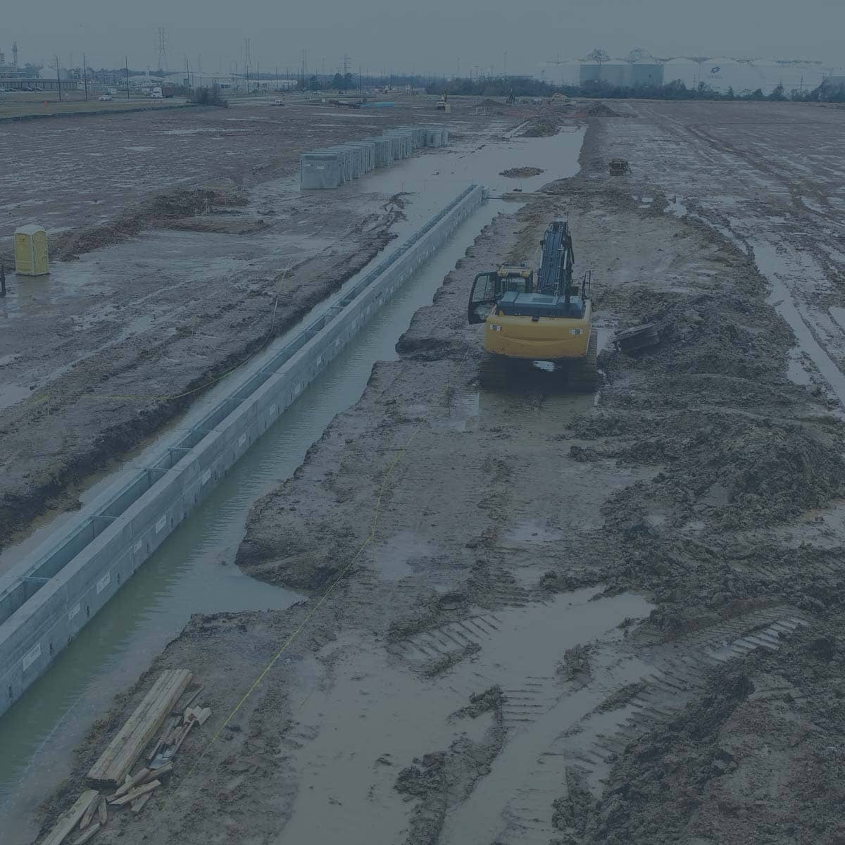
Arguably the most frustrating and time-consuming aspect of an industrial or commercial project revolves around the construction of sloping concrete trench drains.
The ever so subtle slope required to create a positive water runoff flow creates a challenge for the most skilled carpenters and concrete crews to obtain.Pre-fabricating these trench drains often appear unthinkable as each precast section would have to be unique in order to achieve the sloping invert.
Luckily, the precast industry has made great strides in innovative mold designs allowing for efficient and cost-effective manufacturing methods in precast trench drains with an integral sloping floor.
From electrical utility trenches needing a sloping floor allowing for drainage of excess water, to concrete trench drain systems with the sole purpose of conveying sheet drain stormwater runoff from the surface down to underground drain pipe, there are various manufacturing processes to create this integral slope in the precast product.
Trenches on each project are different, but with the advances in mold equipment, the economic value has shifted in favor of prefabricated concrete segments versus in-situ concrete. This along with the inherent advantages of prefabricated construction to reduce the project duration and minimize the downtime and risk associated with weather delays has made sloped concrete trench installation as simple as laying concrete pipe or box culvert.
These precast concrete trench drain systems have started highlighting how important it is to minimize weather delays.The “excavate as you go” construction method with prefabricated trench sections is ideal for wet climates and helps reduce the amount of “mucking out” required after a heavy rain.Gone are the days of excavating and prepping subgrade for hundreds of feet at a time and praying for 2 weeks of dry weather.Now these systems are excavated and installed in half day increments with 50 to 200 feet of sloping trench fully installed each day.
achive.php: you are in the loop slug: marine-port-loading-conditions post_type:post
Heavy duty traffic loading poses many challenges in underground infrastructure construction these days.
Whether expanding terminals at airports, upgrading marine port crane and wharf systems, or industrial sites anticipating large rolling equipment needs, it requires a fundamental understanding of structural design and being able to anticipate potential heavy-duty loading conditions.
“From early on in Locke’s history, we’ve seen many of our contractor partners gravitate towards us to help develop precast concrete substitutes for highly complex and engineered concrete structures at marine port facilities.” says Asher Kazmann, President of Locke Solutions.
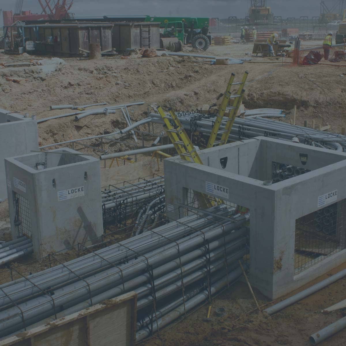
Among the various structures, concrete trench drains, power manholes, and communication handholes rank at the top of the list of underground utility structures needed.“Most projects start with an old cast-in-place specification of concrete manholes and trench drains,” notes Kazmann.“These structures typically have a dense web of reinforcing steel packed into thick concrete wall sections in order to provide the required structural capacity to withstand the massive forklifts, cranes, and non-stop traffic normally associated with busy port locations.”
More and more contractors are gaining experience utilizing precast concrete to speed up their project duration while reducing their safety and weather risks. “Although precast concrete manholes and inlets have become the norm for highway and residential construction, more complex projects such as airports and marine port facilities are slower to jump on the prefabrication trend,” explains Kazmann.“With complex loading conditions, many engineers don’t realize precast is even an option to the old in-situ concrete construction methods.” This trend is slowly evolving as more and more precast manufacturers are developing the expertise to design and manufacture for these unique project conditions.
“After many years working with contractors and engineers in the marine port markets in Southeast Texas, Locke has developed a reputation for successfully converting numerous in-situ concrete structures to custom precast.From concrete trench drains, power manholes, communication handholes, utility vaults, concrete docks, pier caps, and sumps, we have designed structures to handle some of the most intense equipment loads in extreme salty conditions along the coastline.” states Kazmann.
achive.php: you are in the loop slug: concrete-pull-box-recess-design post_type:post
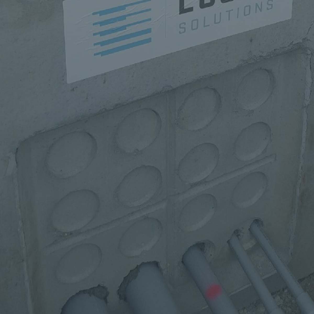
If you have seen the precast concrete pull boxes Locke Solutions manufactures (also known as ground boxes or handholes), you might be asking “What’s up with those round recesses all over the box?”
We sat down with Michael Luck, Vice President of Sales for Locke Solutions, to give us some background on how this look came to be.
“From the beginning of Locke, we’ve always tried to find ways to make precast more valuable to our contractors.” says Luck. “These recesses can be used as a guide in the field and it helps the contractor visualize the location of the duct bank or conduit during installation.”
Luck says, “It’s not as noticeable on the smaller concrete ground boxes, but we also developed these pull boxes with rounded corners.The recesses and the rounded corners both help to reduce the amount of spalling when handling or knocking out openings for conduit.”
Although the precast concrete industry has proven the value of long-lasting steel-reinforced concrete, there have been few changes in precast technology over the years until recently.Many precast manufacturers, including Locke, have started developing new and innovative ways to make the use of precast even more cost-effective and valuable to contractors and owners.
“We believe that if the concrete looks good with little or no chipping, the contractor and the owner feel better about the product.Most of our products are going underground, but we care about how it looks when it leaves our facility and arrives at the site.” Luck reiterates “It just looks better!”
achive.php: you are in the loop slug: new-bridge-crane post_type:post
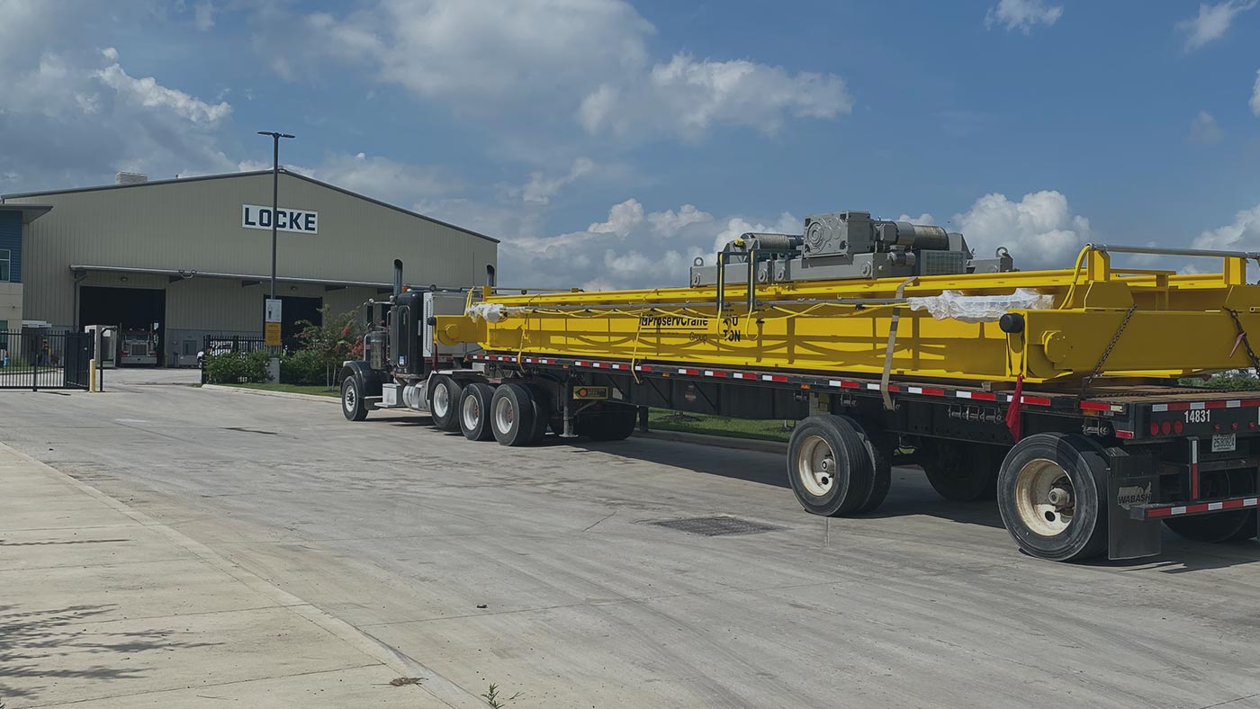
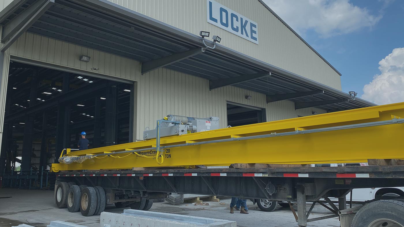
LOCKE CONTINUES TO GROW WITH—AND FOR—OUR CUSTOMERS.
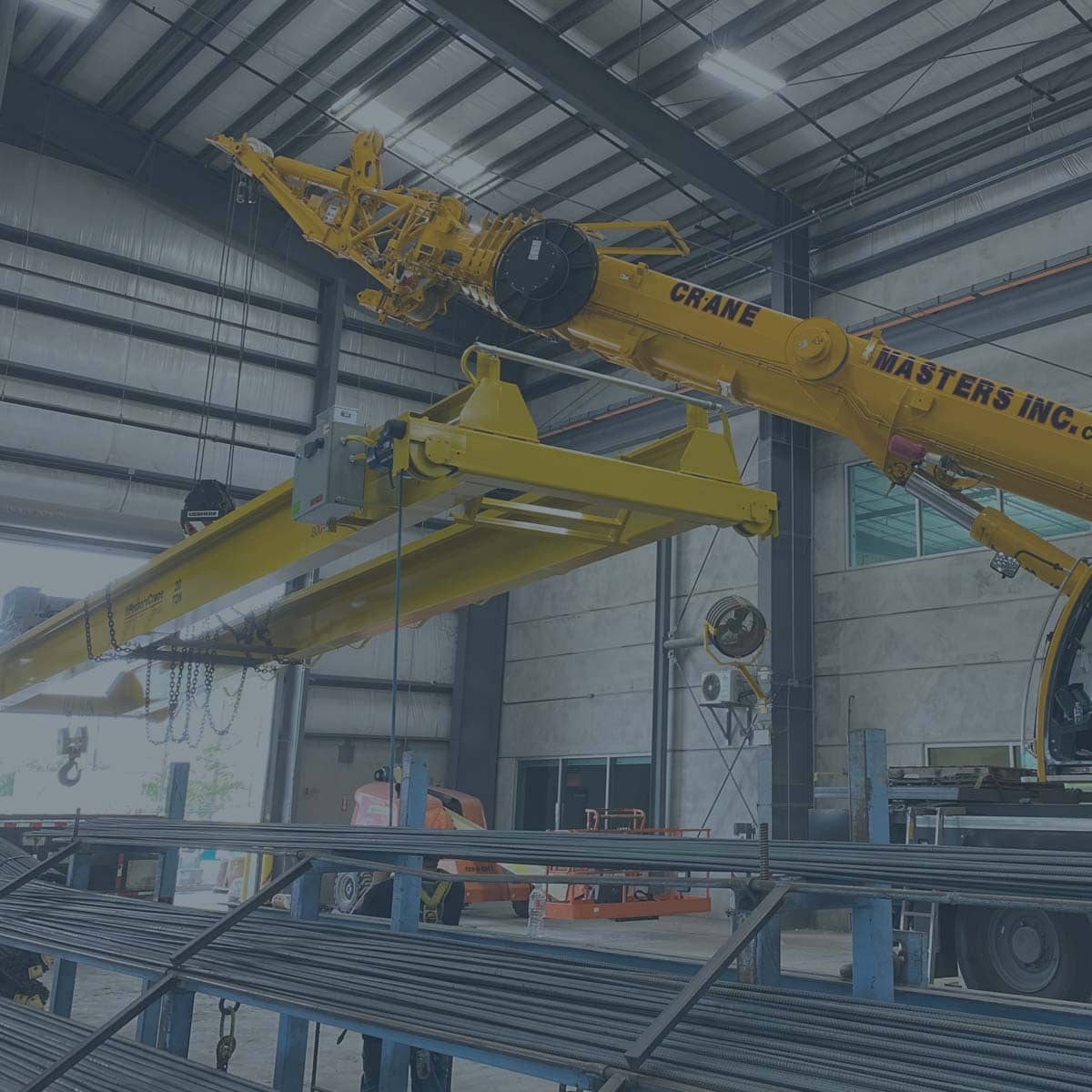
We recently installed two new 45′ long Proserv bridge cranes, one bridge crane in each of our service departments with 50-ton and 20-ton load capacities. Read below for more.
PROJECT PURPOSE
These overhead bridge cranes were installed to increase our handling capacity, productivity, and give us the ability to lift larger precast concrete structures. Plus, the previously installed cranes along with the new cranes allow us to lift up to 100 tons on a single pick inside our facility. “We often design and manufacture large structures such as concrete pits, concrete pier caps, precast concrete columns and beams for pipe rack systems, or aircraft loaded concrete manholes with thick wall sections.” says David Espino, Locke’s Operations Manager. “These structures can easily range from 20 to 100 tons, so having this 100 ton lifting capacity will reduce our manufacturing costs and significantly reduce our overall production lead time.” There is a misconception that prefabricating concrete structures is only possible with smaller structures.
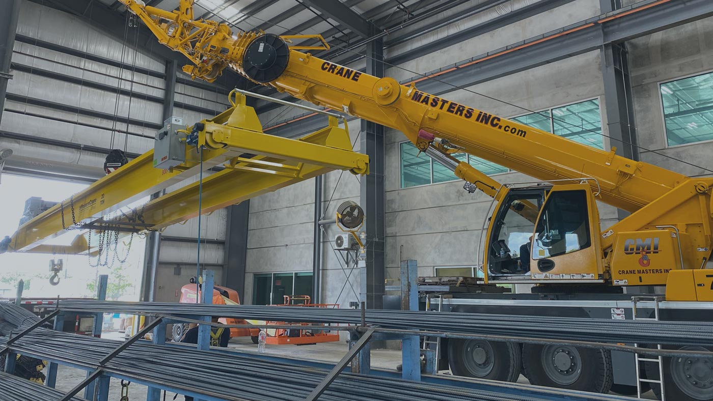
RESULTS OF THE INSTALL
We are now able to provide larger structures to our customers with shorter lead times. Espino notes, “The cranes have also allowed us to be more productive on the manufacturing side increasing our bridge crane count up to 6 within our facility allowing us to perform more crane dependent activities simultaneously throughout the day.” At Locke, we continue to invest in our equipment and facility to keep ourselves ahead of the competition in terms of service and lead time for our concrete products. Our culture is centered around making life easier for our customer.
achive.php: you are in the loop slug: translating-hs-20-traffic-lingo post_type:post
This image shows the potential heavy-duty traffic loading imposed on underground trench structures.
What does HS-20 traffic rating mean?
This is the term used by AASHTO and ACI to describe normal MOVING traffic loading conditions up to 18-wheeler loading. This loading assumes a 16,000 lbs wheel load and therefore a 32,000 lbs axle load. It also takes into consideration the additional loading that occurs from moving vehicles. These loads are called IMPACT and LIVE LOAD SURCHARGE and are an additional safety factors that help prevent underground enclosures from having a structural failure and collapsing in from traffic conditions. There are few construction materials that are designed to withstand these type of loadings other than concrete and cast iron (or ductile iron) steel.
What is the difference between H-20 and HS-20?
Generally speaking, these terms are used interchangeably, but there is a slight difference. You can see the different diagrams showing the difference between H-20 and HS-20. There is minimal, if any, cost savings from designing structures with H-20 versus HS-20, so my recommendation is to always require HS-20 loading if you think there is any possibility of vehicle traffic.
This image helps show the difference between H-20 and HS-20 wheel loading and location.
What does the number “44” represent in HS-20-44?
Quite often, this number “44” is mistakenly assumed to mean 44,000 lbs in some design context. The number “44” actually refers to the year, 1944, in which the HS-20 traffic loading conditions were originally developed by AASHTO.
What is the difference between HS-20 and Tier 22 Ratings?
It is difficult to compare these two designations but there are some key points that people sometimes confuse when dealing with different load ratings. One of the differences between these ratings, is HS-20 refers to traffic loading conditions with wheel loads up to 45,136 lbs, when considering impact and load factors, while Tier 22 is using a 33,750 lbs wheel load tested in a vertical position. The ANSI/SCTE 77 2007 code for the various Tier designations include Tier 5, 8 ,15, and 22 are meant for small boxes with only INCIDENTAL traffic conditions. Any underground enclosures with potential wheel loading conditions should consider using HS-20 traffic loading criteria and materials should be limited to concrete, steel, and/or cast/ductile iron materials.
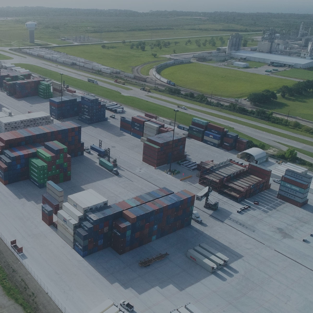
Many marine facilities have heavy-duty loading conditions due to storage containers and the equipment needed to handle these containers.
When do I need to consider designing above & beyond HS-20 traffic rating?
It is smart to consider special designs if you have larger than standard 18-wheeler traffic driving over your structures. Large construction equipment including front loaders, forklifts, mobile cranes all should be considered when installing underground structures. Airport, marine, and railroad facilities should also be looked at closely to determine what type of loading conditions will be present. From a cost/benefit analysis, it is very easy to justify the cost of a heavy duty load design versus the risks of a catastrophic failure because of an unexpected piece of equipment needing access on your structure.
What are the concerns when installing an underground enclosure?
The most critical factors include the type of loading conditions that could create a structural failure leading to the collapse of the enclosure. Vehicle loads on top of the enclosure dictate how the top and bottom of the enclosure should be designed. Lateral loads from soil, water, and loading derived from moving vehicles impact the design considerations of the side walls of an enclosure.
What is the difference between HS-20 and HL93?
HS-20 is the truck live loadings of the AASHTO specification, where H stands for highway, S stands for semi-trailer, 20 stands for 20-ton weight of the tractor (first two axles). Each axle will carry the loads as follow, the first axle carries 8,000 pounds, the second axle, 14 feet away carries 32,000 pounds and a single-axle semitrailer 14-30 ft away from the second axle carries 32,000 pounds.
HL93 is the Basic LRFD Design Live Load, where H stands for Highway, L stands for Loading and LRFD stands for Load and Resistance Factor Design. The HL93 design loading consists of a combination of “Design Truck Plus Design Lane Load” or “Design Tandem Plus Design Lane Load” which ever produces the worst case. A “Design Truck “is same as the HS-20 load. The “Design Tandem “consists of two axles, each axle weighing 25 kips spaced 4 ft apart. The Design Lane Load is equal to 640 pounds per linear foot. This uniformly distributed load is designed to apply on the above grade bridge deck but It does not apply to below ground structures per ASTM C1577.
achive.php: you are in the loop slug: new-precast-redistair-installation-midtown-high-rise post_type:post
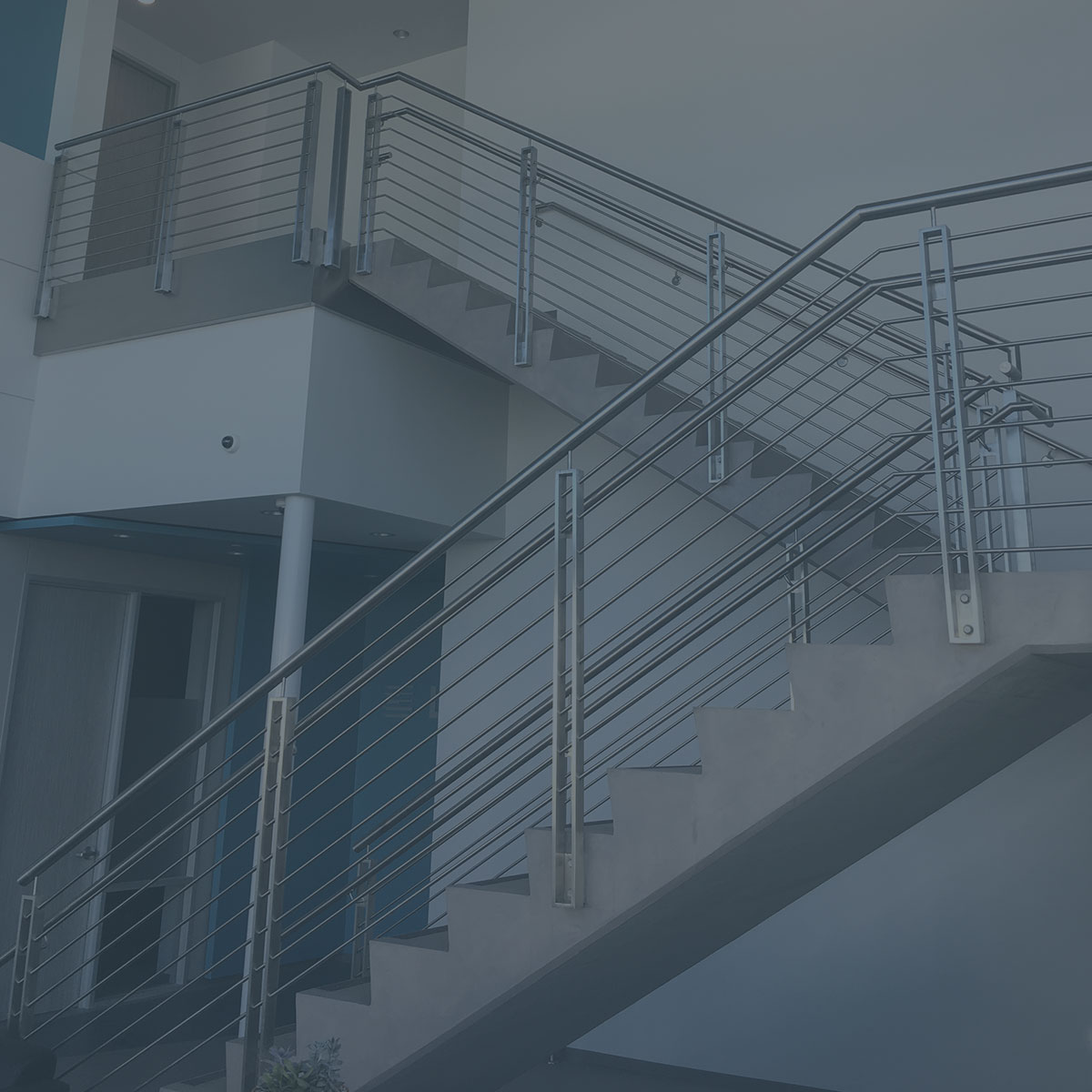
RediStair® is the high-strength precast concrete stair system that brings the value of a concrete stair to a building owner at a cost competitive with steel stair systems. The advantages of concrete stairs over steel are many; they are more durable, quiet, and architecturally appealing than steel or steel frame with concrete tread systems.
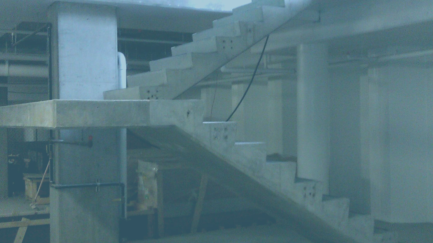
RediStair® is a proprietary process that integrates precast concrete stair stringers and site cast main and intermediate landings to form a “cantilevered truss” that has an unsupported mid-landing. It can be used inside cores, adjacent to cores, mid-slab, projecting off the building, as well as with steel frame construction.
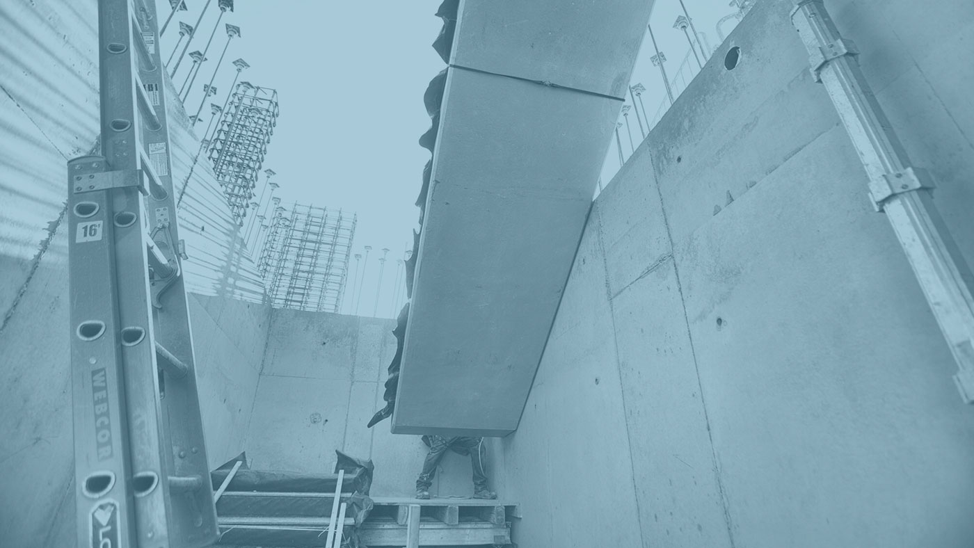
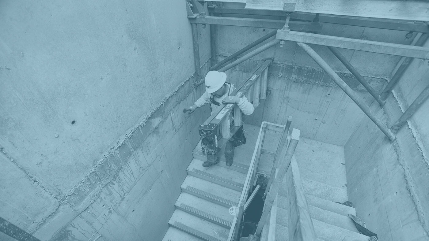
This is the first project in Texas utilizing this patented precast process. Locke Solutions was chosen to fabricate this project due to Locke’s extensive experience with complex precast designs and the capacity of the new Locke facility. Our stairway spans 29 stories with 3 stairwells. The stairs add a safety factor to the project because as the building goes up, so do the stairs. This negates the use of unsafe and inefficient temporary ladders for passage of men and material.
achive.php: you are in the loop slug: precast-concrete-dock-system post_type:post
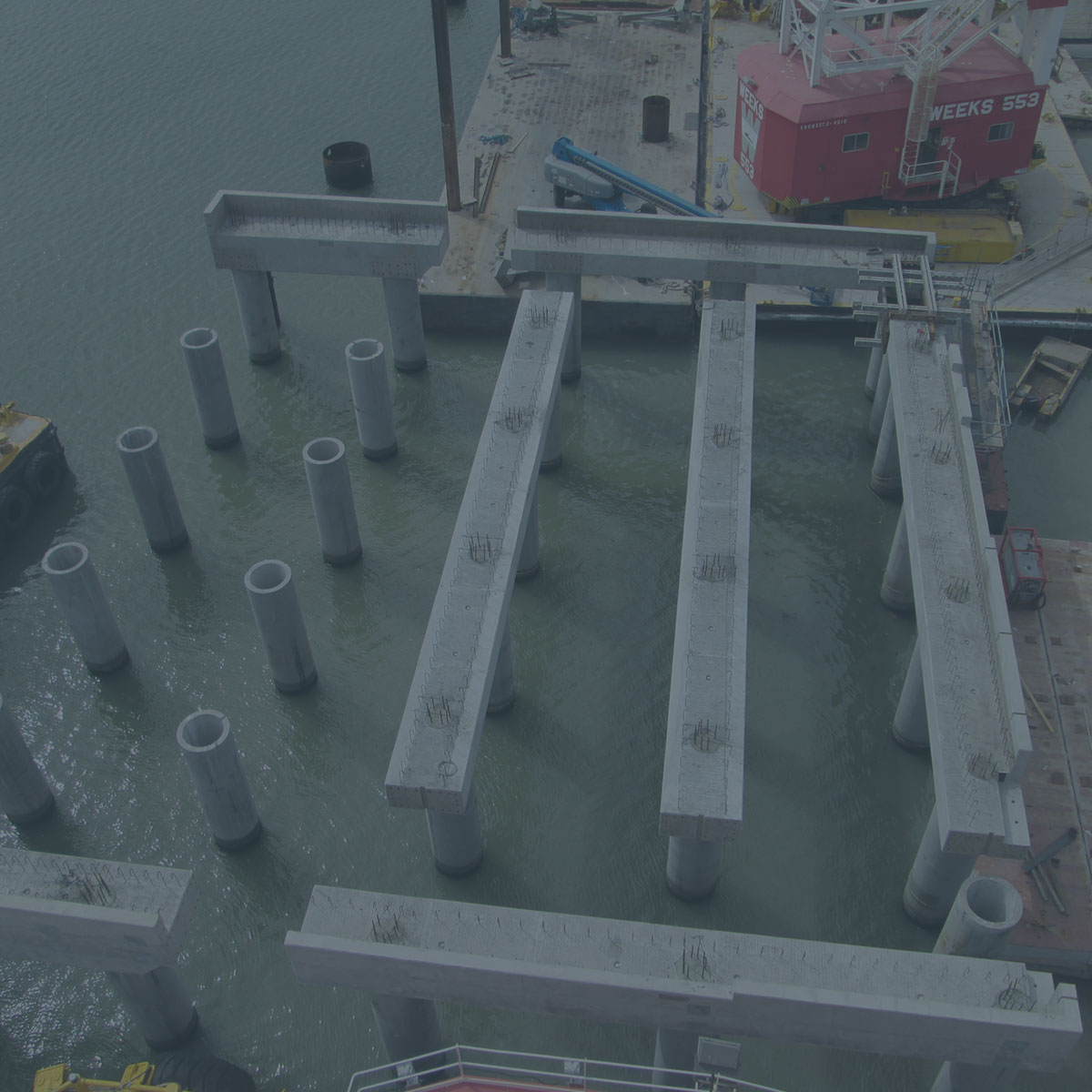
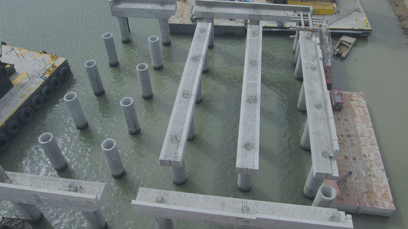
Locke provided several key components towards the construction of a concrete dock platform down in Freeport, TX for the LNG industry. The concrete dock system was originally designed with a pour-in-place concrete beam system supported with concrete piles. In a design/build effort, Locke worked in conjunction with the customer to develop precast concrete pier cap beams to dramatically reduce the project schedule and cost. Locke’s engineering department utilized 3D modeling tools to ensure a perfect fit between precast components and eliminate any potential conflicts.
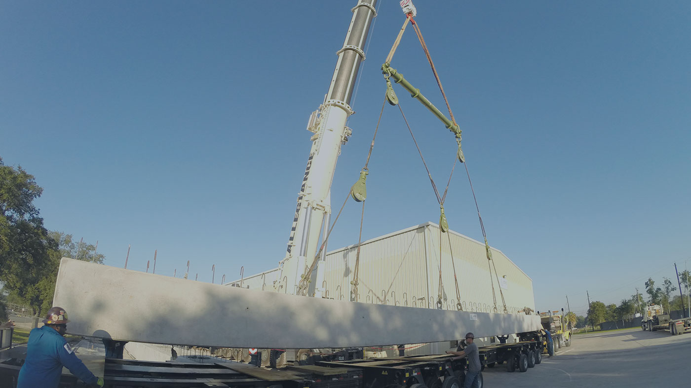
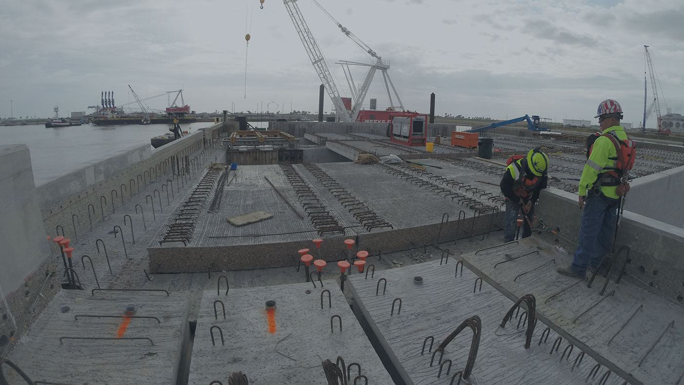
The final outcome resulting in 9 large beam sections weighing as much as 215,000 lbs and as long as 70 feet in length along with 40 precast concrete deck panels spanning the beam sections and creating a working platform to finish the 100’x100’ concrete dock system on.
Hundreds of bar couplers were used to aid in closure pours between beams and the entire concrete system was produced with exposed reinforcing steel and the surfaces were treated to create a roughened surface to adhere to the final “bathtub” concrete pour to finish off the top surface. All of these precast elements were produced and shipped from our facility here in Houston, TX.


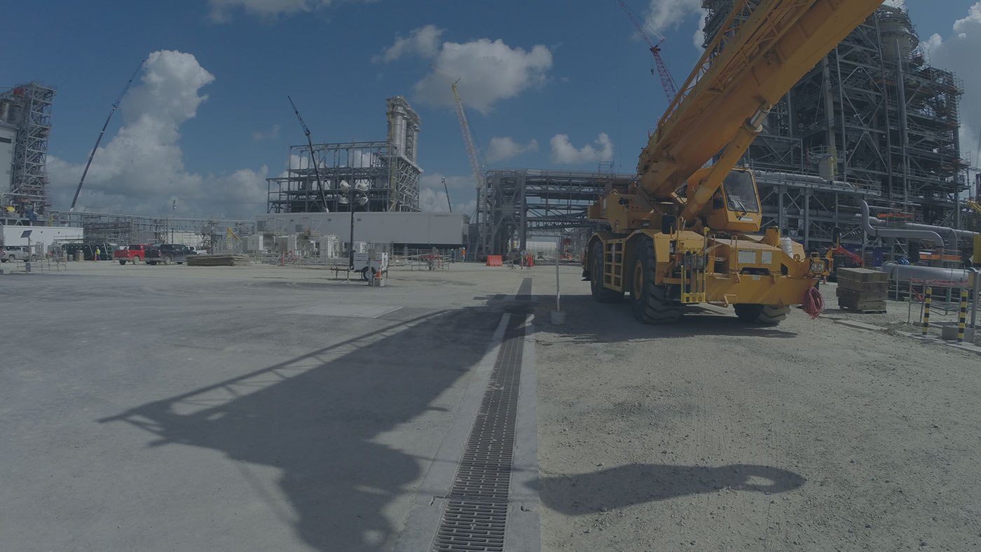 This image shows the potential heavy-duty traffic loading imposed on underground trench structures.
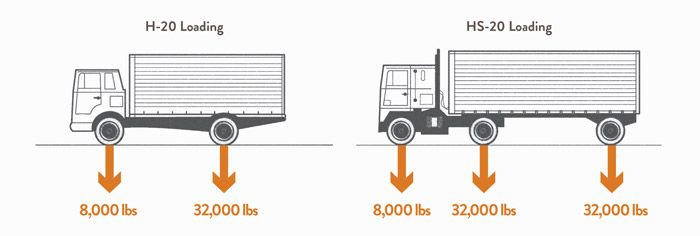
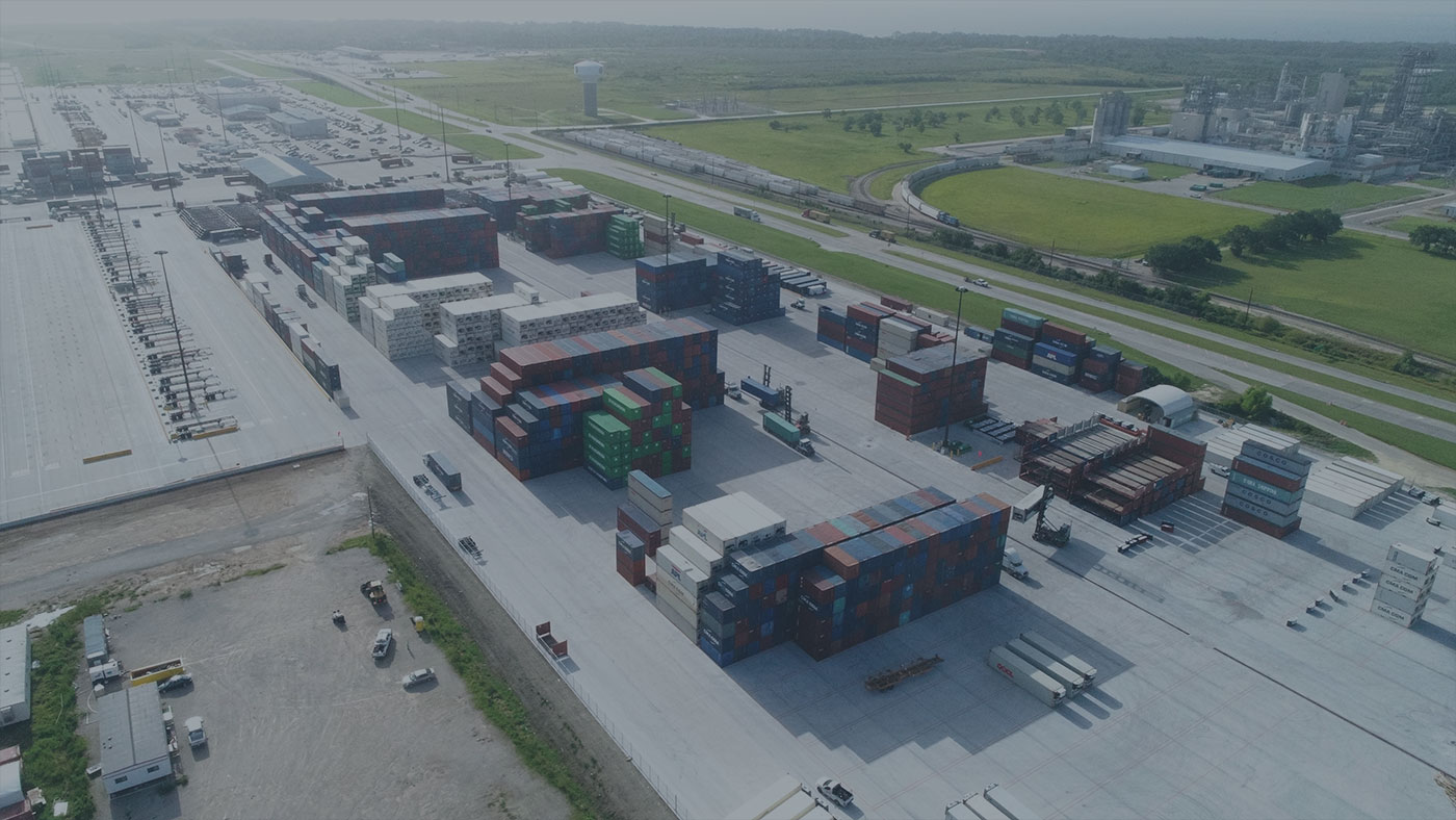 Many marine facilities have heavy-duty loading conditions due to storage containers and the equipment needed to handle these containers.